|
|
|
|
|
|
Collins 180L-2 and 180L-3 Automatic Antenna Tuners.
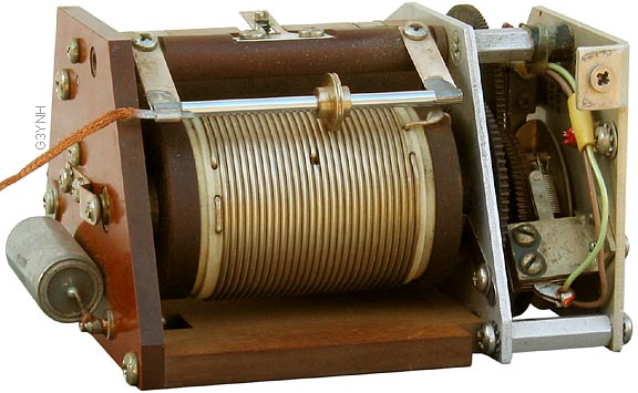
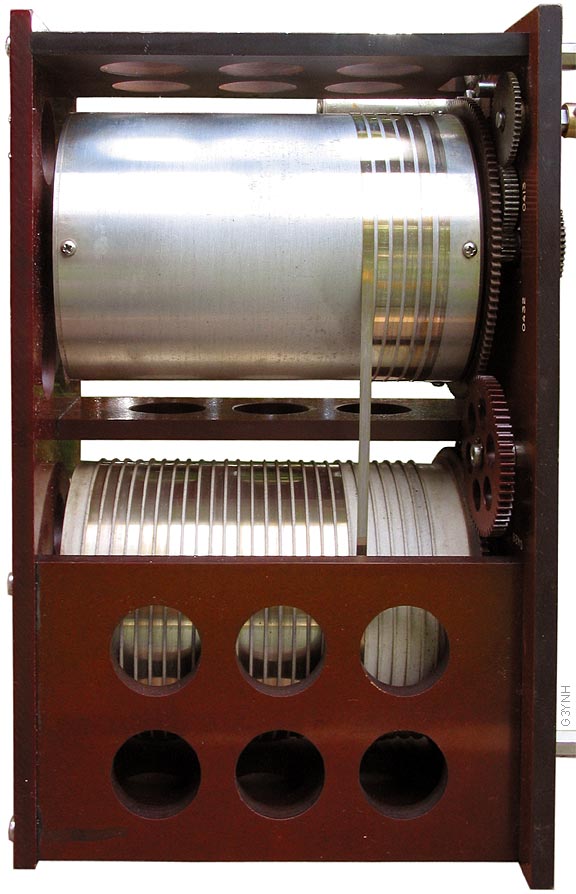
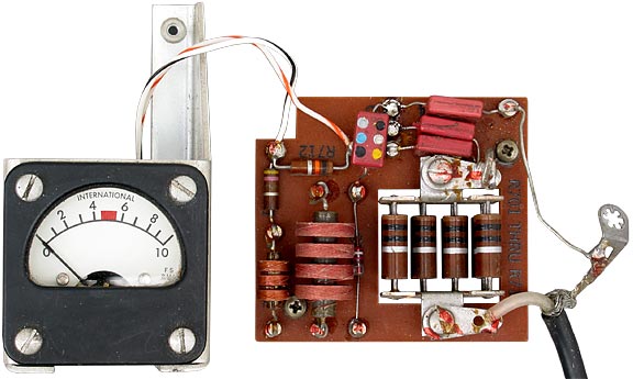
| The 180L-2 and 3 are stand-alone automatic ATUs for use with aircraft transmitters of 50-150W output in the frequency range of 2-25MHz. The 180-L3 is identical to the 180L-2 except for tha addition of an antenna changeover relay. The ATU is designed to match end-fed antennas of between 45 and 100 feet (13.7-30.5m) in length to 52Ω. An impedance magnitude (|Z|) bridge is used to drive a servo amplifier controlling a motorised variable (roller-coaster) RF auto-transformer. A phase bridge is similarly used to control a series conjugate reactance, consisting of a motorised vacuum capacitor in series with a motorised coil and shorting-drum assembly. Both bridges are based around a single current transformer using a powdered-iron toroid, the primary being a silver-plated brass rod [no Faraday shielding]. An input "SWR" [i.e., impedance] indicator uses a "modified Schering bridge" (capacitive ratio arms and a 1Ω resistor for the current arm). |

|

|

 |
|
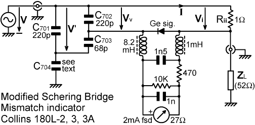
The capacitor ratio-arm bridge used as a mismatch indicator in
the Collins 180L-3 automatic antenna tuner is shown above. This
is a somewhat peculiar circuit, and in such cases it is always
instructive to try to find out what the designer had in mind.
The bridge uses a 1Ω resistor (labelled Rii)
as the current sampling arm, this being constructed by placing
ten 10Ω resistors in parallel. The detector is a simple
shunt-diode rectifier (discussed in the article 'Diode
detectors'), which is a reasonable choice in situations where
the detector must be left floating with respect to ground because
it allows the DC signal to be extracted through RF chokes with
minimal effect on the AC balance. Note that a larger inductance
is used on the side connected to the ratio arms because this
point is strongly susceptible to the effects of stray capacitance.
Notice also that the meter wiring is not decoupled to ground,
since allowing it to float free minimises any upsets to the balance
condition resulting from imperfections in the chokes. The upshot
is that the meter wiring is slightly 'hot' at radio frequencies,
but when installed in the instrument chassis the circuitry is
situated between two earthed bulkheads well away from anything
which might be affected by it. So far everything is easily comprehensible,
but then we come to the question of why the ratio arms were constructed
using four capacitors instead of two. Notice in the figure above that the various voltages appearing across parts of the bridge have been labelled with respect to the generator live terminal rather than to ground. This has been done to simplify the analysis. From the nomenclature used, it should be obvious that the capacitor network forms a two-step potential divider; the voltage Vv being obtained from the voltage V' by means of a potential divider comprising C702 and C703, and the voltage V' being obtained from the generator voltage V by means of a potential divider comprising C704 and the combination of C701, C702 and C703. We can write expressions for the potential divider outputs by stating the capacitor impedances explicitly, but since the -j/2πf parts will always cancel, we need only use the 1/C parts of each impedance. Hence: Vv = V' (1/C702)/[(1/C702)+(1/C703)] = V' C703/(C702+C703) = V'×68/(68+220) = V'/4.235 If we let C' represent the the combination capacitance of C701, C702 and C703, then: C' = C701 + C702C703/(C702+C703) = 220 + 220×68/(220+68) = 271.944pF and V' = V C704/(C'+C704) Now, the bridge will balance when Vv=Vi; and it is stated in the manual that balance occurs when the load ZL has been adjusted to 52Ω resistive. Thus, when the load is 52Ω: Vi = VRii/(Rii+52) = V/53 Hence C704 must be chosen so that Vv=V/53, i.e.: V/53 = Vv = V'/4.235 = V [C704/(C'+C704)]/4.235 C704/(C'+C704) = 4.235/53 = 1/12.515 (C'+C704)/C704 = 12.515 C'/C704 = 11.515 C704 = C'/11.515 = 23.6pF The only problem with this derivation is that C704 is stated in the manual to be 10pF. This value gives Vv=V/119.4, i.e, it causes the bridge to balance when ZL = 118.4Ω. This perplexing result led the author to recheck his working several times, but no mistake could be found. It seemed likely at this point that there must be an error in the circuit diagram, but when it was compared with the parts list, both C703 and C704 were found to be listed as 10pF, which only made matters worse. To resolve this issue, a 180L-3A tuner was dismantled and the bridge was removed for inspection, whereupon it was found that the capacitors fitted were as stated in the circuit diagram. At times like this reality must be the arbiter, and so a test was performed using a radio transmitter and a variety of load resistors, using the same transmitter output voltage in each case and noting the meter reading. Using loads of 50, 61, 70 and 105Ω, it was found that the meter reading diminished progressively as the load resistance was increased, with only a very small degree of imbalance with the 105Ω resistor connected, i.e., the bridge did not balance with the design load impedance connected, but with a load somewhere in excess of 100Ω as calculated from the component values. Finally, to prove the point, a 30-30pF trimmer was connected across C704 and adjusted to balance the bridge with a 50Ω load connected. The trimmer was then carefully removed and its capacitance was measured. At 2MHz, the required trimmer capacitance was determined to be 10±2pF, and at 25MHz the required capacitance was 15±2pF, the variation with frequency being attributable to parasitic inductance (the bridge could benefit from miniaturisation). The original 10pF capacitor had a tolerance of ±10%, so the C704 value needed to balance the bridge for 50Ω loads was found by experiment to be 20±3pF at 2MHz and 25±3pF at 25MHz; the compromise value being about 22pF. The calculated value for balance with a 50Ω load is 24.6pF, the difference between theory and experiment being attributable to component tolerances, measurement error, and stray capacitance. Thus it transpires that the mismatch indicator bridge of the Collins 180L-3 has a design flaw. Fortunately, the indicator has no influence on the operation of the impedance matching system. It was mainly intended to be viewed during pre-flight radio checks, in which case it would still have performed its principal function, which was that of detecting open or short-circuit antenna connections. We now return to the question of why the ratio arms were constructed using four capacitors instead of one large one and one small one. The arrangement used in fact only serves to increase the output impedance of the voltage splitting network. This will not affect the balance point because, at balance the current flowing in the detector is zero and the network is not loaded. What it will do is reduce the sensitivity of the bridge and hence the magnitude of imbalance readings at low frequencies, which may help to offset a falling response of the detector at high frequencies. |
|
References: |
© D W Knight 2007.
|
|
|
|
|
|
u