Nixie Tube Power supplies:
| HT supplies for Nixie tubes are awkward to implement with current commercially available mains transformers. Consequently, when salvaging the tubes from old equipment, be sure also to salvage the mains transformer or DC to DC converter that powers them. Make a note also; of the anode series resistance, and the decimal point cathode series resistance used in the original circuit. |
|
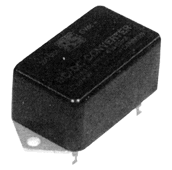
DC to DC converters: RS 591-455 (discontinued). |

|

|
|
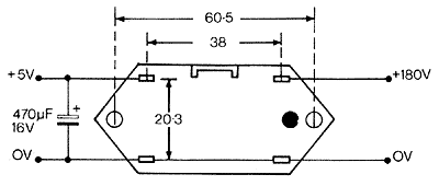
Encapsulated d.c.-d.c. converter which steps up voltage from
5 V to 180 V and drives gas discharge displays. Maximum load
6 digits. Minimum load 47 kΩ. To drive one digit only,
place 120 kΩ in parallel with the output. Output will not
be damaged under short-circuit conditions. Note: 470 μF capacitor across input is essential. Specifications: Vin 5 V d.c. ±0.5 V Vout 180 V ±10% Iout 4 mA min., 15 mA max. Efficiency typically 75% Output ripple voltage 1 V pk-pk max. Operating temp. range 0 °C to 60 °C |
|
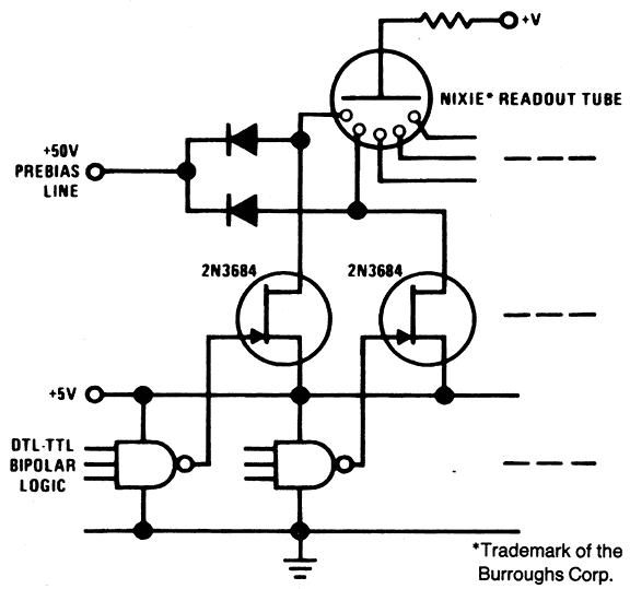
Conventional HT Supplies: The vast majority of Nixie tubes require an HT supply of 170 V - 200 V when used with the SN74141, the maximum allowable voltage being the tube maintaining voltage + Vce(max) for the driver transistor; i.e., typically 140 + 60 = 200V. The greatest danger to the 74141 output transistors occurs when all outputs are off , since the tube anode is then at HT potential rather than at the maintaining voltage; for which reason, it is better to blank leading zeros by disconnecting the tube HT (with a transistor or a relay), than by applying invalid codes to the 74141 input as recommended in the data sheet. The mains transformer used traditionally for displays of 4 to 20 tubes was 125 - 0 - 125 V, 50 mA DC, with a load regulation factor of about 10%. This gives 176 V @ 50 mA load, and 194 V off load, assuming an exact voltage selector tapping (one may assume ≤2 mA per tube if the tubes are operated for long life rather than maximum brightness). Unfortunately, 125 - 0 -125 V mains transformers are no longer standard catalogue items, but transformers with 2 × 55 V windings are. 110 V, bridge rectified, with a load regulation factor of 10%, gives 154 V- 169 V, which can be stacked on top of a 20 V supply (eg., the raw DC supply to a 13.8 V regulator) to obtain approx. 174 V - 189 V. Voltage selector tappings, if provided, may be used to fine tune the HT to the desired 180 V, although over-running transformers is not advisable. It is also possible to regulate a 250 V supply using a 180 V zener diode and a high-voltage series-pass transistor, although such regulators do not take kindly to short-circuits, and tend to fail in an over-voltage condition. If a transformer with a 30 - 0 - 30 V or a 60 V winding is available, a full-wave voltage-doubler can be used to obtain a supply of around 170 V - 185 V, which may be fine-tuned by stacking onto lower voltage supplies and adjusting voltage selector tappings as necessary. Under no circumstances must a capacitor be connected from the tube anode to ground. Gas discharge tubes have a negative-resistance characteristic, and will oscillate if provided with a parallel capacitance (cf., neon relaxation oscillator). Such oscillations may be heard as broadband noise, well into the low VHF. For this reason, the stray capacitance at the anode terminal should be kept to a minimum; and in radio applications, the tubes should be checked for oscillation at the prototyping stage. In general, most tubes will not oscillate if the anode resistor is connected by means of the shortest possible PC track, but the occasional badly-behaved tube might be met. If oscillation cannot be cured, and a replacement tube is unavailable, supply filtration, and a fine wire-mesh behind the display window (to turn the display compartment into a Faraday cage) might provide an alternative solution. Tube Haze and Pre-Bias: Pre-bias is not normally used when driving tubes with the 74141. Note also that the 74141 specification precludes the use of resistors to pull the collectors above 60V, regardless of the tube manufacturer's recommendations. The output transistors can however be protected from over-voltage using diodes as shown below. A dark-red or orange filter in front of the display generally eliminates the need for pre-bias, and also improves contrast. Note however, that acrylic filters (perspex, plexiglass), are ineffective at removing UV haze, and a UV filter may be helpful when photographing tubes that use a mercury-neon fill gas (i.e., the ones that have a cyan-coloured glow in the bulk gas discharge). FET Nixie Drivers: From National Semiconductor Corp. Linear Applications Databook 1986 (page 111). |

| The 2N3684 JFETs are used as Nixie tube drivers. Their Vp of 2 - 5 volts ideally matches DTL-TTL logic levels. Diodes are used to a +50 V prebias line to prevent breakdown of the JFETs. Since the 2N3684 is a TO72 (4 lead TO18) package, none of the circuit voltages appear on the can. The JFET is immune to almost all of the failure mechanisms found in bipolar transistors used for this application. |
© D W Knight, 2002 - 2013
Home | Nixie index page