|
|
|
|
|
|
6.2 Current Transformers: Part 1.
|
6.2-1. Ampere turns and transresistance. 6.2-2. Equivalent circuit. 6.2-3. Working models. 6.2-4. Secondary reactance. 6.2-5. Coupling factor |
6.2-6. Dimensionless transfer function. 6.2-7. Output impedance. 6.2-8. Turns ratio 6.2-9. Insertion impedance and insertion loss. . |
|
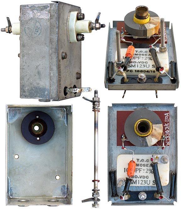
Introduction: From a theoretical point of view, a current transformer is just a conventional transformer; but it holds a few surprises for the circuit designer because, for a given input current, it controls its own input voltage according to the secondary load. Since voltage and current have a reciprocal relationship, anyone used to thinking in terms of voltage may find that changes to a current transformer network sometimes have the opposite of the desired effect. Hence, given that there are peculiarities, we will spend some time looking at the basic properties of current transformers before attempting to incorporate them into bridges. From a practical standpoint, it is usually best to design a current transformer so that there is very tight coupling between the primary and secondary windings; and in RF applications, this implies the use of a ferrite or powdered-iron toroidal core. A two-hole (binocular or 'pig-nose') core gives even tighter coupling, but the topology prevents single-layer winding of the secondary and is therefore usually rejected on the grounds that it gives rise to additional parasitic capacitance. The current transformer is effectively an impedance step-up device, where the impedance terminating the secondary appears in series with the signal path but scaled down according to the square of the turns ratio. It follows that if the secondary is not terminated, the transformer primary inductance will appear in series with the signal path (and the secondary voltage will be shifted in phase with respect to the primary current by approximately 90° as a result). Also, conversely, the transformer may effectively be removed from circuit by shorting the secondary, in which case the primary impedance falls practically to zero. In toroidal transformers, a one turn winding is obtained by passing a wire once through the hole in the core. The primary of an RF current transformer is usually a single turn, made by pushing a short length of coaxial cable through the hole. The outer braid of the cable (when grounded) acts as a Faraday shield, preventing direct capacitive coupling between the primary and secondary windings. The shield must only be earthed at one end to avoid producing a shorted turn (earthing both ends of the Faraday shield is another way of switching-off the transformer). To reduce losses, the coaxial cable used should preferably have silver-plated or plain copper conductors and PTFE (Teflon) dielectric. Since the outer coating is also in the transformer field, this should be made from PTFE, FEP, ETFE or similar non-polar low-Tanδ material. If PVC covered cable is the only type available; the outer sheath can be removed, and the braid can be insulated by wrapping it with plumber's PTFE joint-sealing tape. Polyethylene dielectric is not recommended because it will melt during soldering and it may also melt in service if the transformer core gets hot. Faraday shielding is optional (and not always beneficial) and when it is used, it is not always shown explicitly on circuit diagrams. |
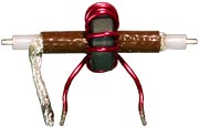 |
Faraday shielded current transformer. |
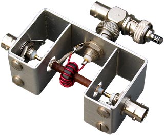
| Notice, in the photograph below, that the Faraday shield is connected to the secondary network grounding point. The reason for doing so is that the chassis on which the transformer is mounted is also the return path for the primary current. The chassis has some inductance, and so a voltage that increases with frequency develops between the primary input and output ground connections. Since there is a capacitance of several pF between the Faraday shield and the transformer secondary winding, and the reactance of this capacitance falls with frequency; a disturbance of the transformer frequency response will occur unless the shield is maintained at the secondary network reference potential [for experimental confirmation see Amplitude response of conventional and maximally flat current transformers, by DWK]. |
 |
 |
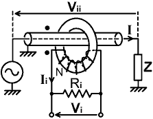
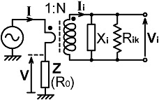
| In the diagram above, dots are used to indicate the phasing of the windings, i.e., the ends of the windings are marked in such a way that they can be considered to start (or pass into the hole) together. When this convention is observed, the arrow shown for the secondary voltage indicates the polarity in which it is in phase with the primary voltage (assuming ideal transformer behaviour). The primary voltage Vii is, of course, the voltage drop that results from inserting the transformer into the signal path. The current in the secondary is 180° out of phase with the current in the primary, i.e. (insofar as the concept of 'flow' can be used), when current flows into one end of the primary, current flows out of the corresponding end of the secondary. |
|
6.2-1 Ampere turns and transresistance: In order to obtain design equations for the current transformer, it is sensible to begin by assuming that the reactance of the secondary winding is very large in comparison to the secondary load resistance and can therefore be ignored. This is a simplification that applies approximately when the transformer is working in the middle of its useful frequency range, for which reason we will sometimes refer to it as the mid-band analysis. To obtain the mid-band input-output relationship, or at least a reasonable approximation to it, we start by assuming that the behaviour of a small toroidal transformer wound on core material chosen according to the manufacturer's instructions is ideal. The equations describing the transformer can then be deduced on the basis that the primary magneto-motive force (MMF) is equal to the secondary magneto-motive force; this quantity being simply the product of the current and the number of turns (MMF is also known as "ampere-turns", which are its units). When dealing with RF current transformers; we can normally use a single number 'N' to express both the secondary turns and the turns ratio, because the number of primary turns is usually one. Thus, using the definitions given in the diagram above, we may write the ampere-turns rule: I = N Ii The secondary current thus being determined, we may obtain the secondary voltage: Vi = Ii Ri and hence:
The quantity Ri/N is the transfer-resistance, or transresistance of the current-transformer network. It is analogous to the transresistance of an amplifier that gives an output in volts for an input in amps; i.e., it is a gain-figure with dimensions of Ohms. By analogy with the transconductance or 'mutual-conductance' Gm of an FET or valve, we will give it the symbol Rm. In the approximation that the transformer is ideal, it becomes the nominal transresistance, i.e.; Rm(nom) = Ri / N It is a useful figure to keep in mind when designing with current transformers. E.g.; A current transformer with a load resistance of 50Ω and a turns-ratio of 10, has a nominal transresistance of 5 Volts per Amp. A current transformer with a turns-ratio of 20 and a 56Ω load has Rm(nom) = 2.8 V/A. |
|
6.2-2. Detailed equivalent circuit: Practical current transformers are, of course, far from ideal, and the issues that need to be taken into account when working with them can best be understood by considering the equivalent circuit shown below. This circuit is obtained by reversing the conventional model for a voltage transformer and referring all parameters except core loss to the secondary side. Core loss is best associated with the primary side because it still exists if the secondary winding is removed. |
 AL = inductance factor |
Rμ = core loss Li = coupled secondary inductance LL = leakage inductance RW = winding resistance Rε = dielectric loss Ci' = "self-capacitance" |
|
The equivalent circuit implies that the transformer leakage inductance
(i.e., the inductance that manages to escape from inclusion in
the coupling between windings) will appear in series with the
output; so affecting the magnitude and phase of the voltage across
the secondary load resistor (not shown). Our best course of action
is to try to minimise it, which we have done to some extent by
choosing to use a toroidal magnetic core; but it is also important
to keep the primary winding close to the core (i.e., the hole
in the core should be as small as possible), and to keep the
magnetic-circuit path-length short (the outer core diameter should
also be small). One consequence of leakage inductance is that
the inductance obtained by measuring the secondary winding (Lsec=Li+LL)
is always slightly greater than the inductance obtained by least-squares
fitting to the transformer frequency-response data (the latter
being a good approximation to Li). The
difference for a small toroidal core is usually in the region
of 1 or 2%, being worst for low-permeability cores. The winding resistance is also in series with the output, which would not be serious except that it is not the DC resistance of the wire that matters, but the RF resistance, and this varies with frequency. The sensible recourse is therefore, once again, to minimise it; which means that tinned wire is forbidden, and the coil should be wound with enamelled copper or silver-plated wire. The wire diameter should also be reasonably large; except that this is in conflict with the need to keep the transformer dimensions small and avoid overlapping the turns. Some people like to stretch wire to remove the kinks before using it to wind coils. This practice should be avoided because it work-hardens the copper and increases its resistivity. Wire can be de-kinked without work-hardening by stroking it with a soft cloth or paper towel. If the leakage reactance and winding resistance are kept small in relation to the secondary load resistance, then the secondary inductance, the self-capacitance, and the core losses, are effectively in parallel with the secondary load. This means that most of the transformer non-idealities can be lumped into a single impedance in parallel with the secondary winding, a simplification that permits straightforward and effective circuit optimisation. Note however, that the lumped component model breaks down completely at about twice the secondary network self-resonance frequency (the first series resonance of the parallel network). Self-resonance is associated with the length of the secondary winding wire; which means that, in order to achieve a wide bandwidth, the number of turns should be kept low. A compromise is necessary here; because the number of turns also dictates the secondary inductance and, as we shall see, insufficient inductance gives rise to a poor low-frequency response. One component of the model that is not strictly amenable to the lumped-parameter approach is the 'self capacitance'. The self capacitance is largely a fiction, its purpose being to simulate a phase lag in the transformer output voltage that occurs at high frequencies. One cause of the HF phase error is that it takes a finite time for an electromagnetic wave to propagate along the winding wire, i.e., the coil is a transmission line. This transmission line is also dispersive, i.e., the propagation velocity varies with frequency but remains reasonably constant provided that the wire length is considerably less than one half-wavelength at the maximum frequency of operation. Hence there is an inherent inaccuracy in the standard model, but in general we will be able to cope with any noticeable discrepancy by considering the HF phase-shift as a separate phenomenon. One consequence, for example, is that the HF amplitude response of a transformer does not necessarily fall-off as rapidly as the 'self capacitance' would lead us to believe. This means that frequency-response calculations for phase-insensitive circuits such as RF ammeters and magnitude bridges can become more accurate when the self-capacitance is ignored [see Amplitude resp. of conventional and maxflat I transformers]. Note that the 'self-capacitance' is designated Ci'. The reason for the prime is that there will be some genuine parasitic capacitance across the transformer secondary network; due to the capacitance across the ends of the coil and between the lead wires; and due to the capacitance of the load resistor and any detector that might be connected. It also transpires that any parasitic effect that causes a phase shift in the transformer output will manifest itself as a contribution to the apparent self-capacitance (such effects can also cancel the actual self-capacitance and make the apparent self-capacitance negative). Hence the capacitance required for design purposes is: Ci = Ci' + true parallel capacitance + apparent capacitance not due to the transformer itself. Finally, the core loss, being modelled as a resistance, appears to have no consequence except for a small reduction in our expectations for output voltage; but unfortunately, this loss also varies with frequency and so will affect the frequency response. It is therefore important to keep the core loss down, which implies that we should try to choose core materials of low initial permeability. We do not want the core permeability to be too low however, since this will make it difficult to obtain sufficient secondary inductance, and it will allow some of the magnetic field to escape from the core and give rise to leakage inductance. There is also, incidentally, a parallel resistive component due to dielectric loss (shown referred to the secondary); which is why it was stated earlier that plasticised PVC insulation should be avoided, and that the dielectric and coating of the primary coaxial-cable stub should be made from material that has a low Tanδ. The author is aware of published articles on the subject of SWR bridge design that say that the current transformer secondary can be wound with hook-up wire (i.e., PVC insulated, tin-plated wire). Hopefully, from the foregoing discussion, it can be see that this is bad advice. PTFE-coated silver-plated wire can be used, but enamelled (soft) copper is better because the coating is thin, giving the greater conductor diameter for a given overall wire diameter. |
|
6.2-3. Working models: Many RF current transformer circuits in use and in the literature are based on the supposition that the simple ideal transformer model is adequate. This may be true if the transformer is to be used to make an RF ammeter to be operated over a limited frequency range, but it is a poor assumption if the transformer is to be used in a bridge intended to work over several octaves. If the transformer is suitably constructed however, it is possible to simplify the general model by assuming that all of the non-idealities can be represented as a network in parallel with the secondary winding. In that case, the working parameters are no longer strictly identifiable as secondary inductance, self-capacitance and loss resistance because they will have absorbed other non-idealities into their apparent values. The secondary inductance Li, for example, may be adjusted to account for the fact that the permeability of the core material, and hence the AL value, may vary slightly with frequency. The difference will not be great enough however, to warrant adding a prime or recurrent use of the word 'apparent' when discussing it. The point in representing all of the non-idealities as an impedance in parallel form is that the transformer input-output (transfer) relationship can be inverted. The impedance is then converted into an admittance that is readily separable into real and imaginary parts. The real part is the reciprocal mid-band transfer function, and the imaginary part contains all of the information relating to the frequency-response. This simplified quasi-empirical model is capable of describing the current transformer amplitude and phase performance to better than ±0.1% and ±0.1° over five or more octaves [A6.4]. The greatest non-ideality of the transformer is due to the finite secondary inductance. Hence this inductance can never be neglected in design calculations. Capacitance and resistance can however be neglected in certain circumstances. It was mentioned earlier that self-capacitance can often be ignored when designing circuits that discard phase information. It is also possible to devise passive compensation networks that cause a current transformer to behave as though its secondary reactance is purely inductive (to a good approximation) over a wide range of frequencies [A6.4]. We may also note, that if the auxiliary circuit is provided with some gain or sensitivity adjustment, there may be little point in including a resistive element to account for the fact that the transformer mid-band output voltage will be slightly lower than that of an ideal transformer. Hence, the complexity of the model can be adjusted according to circumstance. |
|
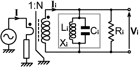
6.2-4. Secondary reactance. In practice, most of the non-ideality of a current transformer can be accounted for by presuming the existence of a reactance Xi connected in parallel with the secondary winding. This reactance is such that the phase of the output voltage leads the phase of the input current at low frequencies and lags at high frequencies, i.e., it is inductive at low frequencies and capacitive at high frequencies. Hence, in the lumped component model shown below, it is represented as an inductor in parallel with a capacitor. When designing wide-bandwidth measuring instruments, particularly bridges, it is necessary to quantify these additional components so that some kind of compensation can be applied. |
|
It is easy to predict the low-frequency
response because a good estimate for Li
can be had simply by measuring the inductance of the secondary
winding (Lsec). As mentioned previously,
the effective value of Li will be about
1% less than Lsec. Li
can also be estimated to within about ±20% by using the
published AL value for the magnetic core,
i.e., Lsec = AL N² |
 |
|
The capacitance is a more problematic however. It is made up
from several components: one being the stray capacitance due
to the connecting leads and the capacitance of the secondary
load resistor Ri; another being the semi-fictitious
'self-capacitance' that represents the propagation delay. It
was mentioned before that there is a subtle difference between
the phase lag due to a lumped capacitance and the phase lag due
to a time delay, and the former will only serve as an approximation
for the latter if the delay is small. To these basic contributors,
we must also add the fact that mismatch of the primary transmission
line, capacitive currents induced in the Faraday shield, and
the inductance of the secondary load resistor, all make contributions
to the apparent or 'effective' secondary capacitance. Hence it
can be difficult to place a value on the effective capacitance,
leading to extremely inconsistent results when traditional approaches
to current-transformer bridge design are followed. We will look into the subject of transformer phase response in considerable detail later, but before we can do that we must incorporate Xi into the mathematical model. The ampere-turns rule can still be applied, i.e. (using the definitions from the diagram above), I=NIi as before, but now Ii has become a fiction because Xi takes a bite out of it before it reaches the transformer terminals. We can still obtain an expression for the secondary voltage however, by presuming Ii to exist and by defining the secondary load as: Zi = Ri // jXi (where the symbol // should be read as: "in parallel with", and a//b=ab/(a+b). Hence: Vi = Ii Zi and since Ii=I/N
|
|
6.2-5. Empirical efficiency factor. Equations (4.1a-c) above generally give a good description of the overall shape of the transformer frequency-response curve, but are a little optimistic regarding the absolute output voltage obtained. The reason is that the transformer is not 100% efficient. In practice, the actual output voltage magnitude can be expected to be somewhere between 96 and 99% of that predicted by the 'ideal transformer with parallel reactance' model [see Current transformer efficiency factor]. The first question we should ask about this discrepancy is; "does it matter?", and the answer is generally "no". The point is that none of the transformer parameters can be predicted with absolute certainty because there are always engineering tolerances to consider. This means that it is always advisable to design circuits in such a way that they can be adjusted during calibration. If we design an RF ammeter to have (say) a ±20% adjustment in the meter series-resistor, or a bridge to have a ±20% adjustment in the ratio of the voltage-sampling network, then a model discrepancy of about 3% will go un-noticed and the instrument will still achieve its design performance targets. Hence there is usually no point in over-complicating the mathematics of the design process. In the event that transformer efficiency is critical however, the shortfall can be accounted for by invoking an empirical coupling factor (k say) and using it to modify the predictions of equations (4.1). One way in which we might elect to use this approach is to rewrite equation (4.1c) as: Vi = I k (Ri // jXLi // jXCi) / N where k has a value of about 0.97. This will do the trick, but it is unsatisfactory in two ways. Firstly, k is not directly identifiable as an electrical component, and this will be a nuisance in circuit simulations. Secondly, when k is multiplied into the impedance bracket, it will affect the resistance, the inductance and the capacitance. Although Li and Ci are affected by the simplifications used to obtain a working model, they still remain closely associated with true physical parameters. They can also be measured in a manner that is unaffected by the choice of Ri (i.e, they have discrete identities). Hence it is more sensible to apply k in such a way that it only affects the apparent load resistance, i.e.:
Rik = k Ri and that we can achieve the same result by placing a resistance in parallel with Ri, i.e.: Rik = Ri // Rk Hence: k Ri = Ri // Rk = Ri Rk / (Ri + Rk) i.e.: k = Rk / (Ri + Rk) which rearranges: k (Ri + Rk) = Rk k Ri + k Rk = Rk k Ri = Rk - k Rk = Rk (1 - k)
Rk = 0.97 Ri / 0.03 = 1617Ω The output voltage of the transformer is, of course, given by:
The only thing that might appear to be unsatisfactory about the definition of Rk, as given in equation (5.2), is that the value of this lumped loss resistance seems to depend on Ri; and Ri is an external load resistance, not part of the transformer. It transpires however, that for transformers with low winding resistance, the efficiency k increases as the load resistance is reduced [see Current transformer efficiency factor]. This means that Rk is approximately constant, i.e., it is largely independent of Ri and therefore a true parameter of the transformer. This is reasonable of course, because Rk is mainly representative of the core loss and the dielectric loss referred to the secondary network. Incidentally, when a laboratory bridge is used to measure the secondary inductance of the transformer, the loss-balance adjustment expressed as a parallel resistance provides a first (but somewhat optimistic) estimate of Rk. Now notice that a better figure for the transresistance (without the 'nominal') is given by: Rm = Rik / N Rm (the mid-band transresistance) is typically about 2% smaller than Rm(nom). Also, we can now define a complex input-output relationship, the transfer-impedance or transimpedance: Zm = (Rik // jXLi // jXCi) / N [Volts per Amp] By computing the transimpedance from fixed values of Rik, Li and Ci (the last of which can be positive or negative), and presuming that leakage inductance, winding resistance and propagation delay are sensibly minimised; it is possible to model the unloaded output voltage to an accuracy of somewhat better than 0.1%, over 4 or 5 octaves, using only four parameters. |
|
6.2-6. Dimensionless transfer function. Although the principal relationship is between the primary current and the secondary voltage, the output of current transformer is also related to the voltage across the load into which the primary current is being delivered. If the voltage across that load is V, and the impedance is Z, then its relationship to the primary current is given by Ohm's law: |
|
I = V / Z Substituting this into equation (4.1a) gives: Vi = V Zi / ( N Z ) (where Zi = Rik // jXi). This allows us to define a dimensionless transfer function:
|
 |
The balance point for a bridge is independent of the voltage
or current associated with the primary load. Hence, when designing
bridges, the use of dimensionless transfer functions preserves
this independence. The design process then reduces to the matter
of defining transfer functions for the current and voltage sampling
networks and setting them to be equal when Z=R0.
In that case, the transfer function for the current sampling
network becomes:
|
|
6.2-7. Output impedance. One of the main applications of the current transformer is that of driving a detector. Thus there are many situations in which the input impedance of a detector forms part of the secondary load. Note that this is not the case when the transformer is incorporated into an impedance bridge and the bridge is at balance; because the outputs of a current sampling network and a voltage sampling network are placed in series opposition and both networks are unloaded when the balance point is reached (no detector current is drawn because the two voltages cancel). It is an issue in SWR bridges however, because SWR measurement involves taking detector readings from bridges that are out of balance, and it is an issue in magnitude and other scalar-addition bridges, because the sampling network outputs are rectified before summation. The easiest way to take care of this matter is to be aware of the output impedances of all of the sampling networks used, and so a derivation for the output impedance of a current transformer will be given here. The output impedance of a network is defined as the impedance that, when placed in series with a hypothetical perfect generator, accounts for the drop in output voltage that occurs when the network is loaded. Shown below is a representation of a current transformer network feeding a detector that has an input impedance ZD. If the load ZD is removed, the output of the network is Vi, but when the load is connected the output sags slightly (and may be shifted in phase) to a new voltage Vi'. This situation is modelled on the right as a perfect generator with an output Vi in series with an impedance Zgi, the latter being the output impedance we wish to determine. |

|
Using the definitions given in the diagram: Zgi = (Vi - Vi') / ID where: ID = Vi' / ZD Hence, combining these two equations: Zgi = ZD (Vi - Vi') / Vi' = ZD [ (Vi / Vi') - 1 ] . . . . . . (7.1) From equation (4.1a) given earlier: Vi = I Zi / N and by considering ZD as part of the secondary load: Vi' = I (Zi // ZD) / N Hence Vi / Vi' = [ I Zi / N ] / [ I (Zi // ZD) / N ] = [ (1/Zi) + (1/ZD) ] / (1/Zi) Vi / Vi' = 1 + (Zi / ZD) Substituting this into (7.1) gives: Zgi = ZD [ 1 + (Zi / ZD) - 1 ] i.e.:
The input resistance of a simple diode half-wave detector was discussed in section 6-9 and shown to be approximately half the detector load resistance. Thus, for example, a detector connected to a meter of 10KΩ resistance will have an input resistance of about 5KΩ. If the detector is connected to a current transformer having a secondary load of (say) 50Ω, then the effective load becomes 50//5000 = 49.505Ω. Hence, if the detector input resistance is 100 times the secondary load resistance, the detector will cause the transformer output to drop by no more than 1%. The derivation given above incidentally, contains a hidden approximation. This is due to the assumption that the primary current I will not change when the secondary load is changed. In fact, since reducing the secondary load impedance will cause the input impedance of the transformer to go down, the current I will increase very slightly when the secondary is loaded. Hence the output impedance of the network is slightly less than indicated by the derivation. If however, we stick to the practice of making the transformer input impedance less than 1% of the primary load, and make the detector input resistance at least 10 and preferably 100 times greater than the secondary load resistance, then the deviation will be at the 0.1 to 0.01% level and can safely be neglected. There is also, of course, an approximation inherent in neglecting the transformer losses. This can be overcome by replacing Ri with Rik=Ri//Rk (losses reduce the output impedance slightly) but it is rarely necessary to consider such subtleties when determining load driving capability. |
|
6.2-8. Choosing the turns ratio: The principal input-output relationship for a current transformer was given earlier as: Vi = I Zi / N If we just want to know the sensitivity of the device, we can ignore the phase information in this expression by taking the magnitudes of both sides: |Vi| = |I| |Zi| / N We can also argue that, if the secondary load resistance Ri is low enough to swamp the transformer reactance, then phase errors will be small and |Zi| will be approximately equal to Ri. Hence the mid-band sensitivity of a current transformer (neglecting losses) is given by the expression:
If a sampling network is to drive a simple passive indicating device such as a half-wave rectifier; good detector linearity can be obtained with an output voltage of about 7V RMS, which gives 10V after rectification. Output voltages greater than that give improved linearity of course, but when using signal diodes, it is advisable to allow a large safety margin with regard to reverse breakdown. Lower voltages are acceptable when the actual meter reading is unimportant, i.e., for null indicators; but if the maximum voltage after rectification is much below 1V, the linearity will be poor and, due to the diode forward threshold, nulls will become broad and difficult to locate. Hence, for our purposes, a reasonable design window for current transformer output is 1 to 10V after rectification, i.e., |Vi| between about 0.7 and 7V RMS. If the indicating device is a (readily available) 100μA meter, then padding its resistance to 100KΩ gives a sensitivity of 10V DC for full-scale deflection (FSD) with a detector input resistance of 50KΩ; and padding it to10KΩ gives 1V for FSD and an input resistance of 5KΩ. It is common practice to load the secondary of a current transformer with a resistance of about 50Ω. This choice usually permits a transformer bandwidth of 5 octaves or more, gives sensible turns ratios for useful output voltages, and enables detectors of 5KΩ input resistance to be connected with only about 1% drop in output. There is also the advantage that a 50Ω load resistor can be replaced by an arbitrary length of coaxial cable with a terminating resistor at the far end, a possibility that facilitates testing and allows the detector to be placed some distance from the transformer. The table below shows the number of turns required in order to obtain a given output voltage for a given primary current when the transformer secondary is loaded with 50Ω. The left-most column shows the generator output power required to produce the current when the generator is working into a 50Ω load. The candidate output voltages correspond to 10V, 3.16V (i.e., √10V), and 1V after rectification (neglecting diode forward voltage drop). The actual number of turns used must, of course, be an integer (i.e., a whole number), and so for a practical transformer the number must be rounded up or down. |
| Table 6-16#1. Relationship between current transformer output voltage and no. of turns. |
|
|
|I|=√(P/50) |
N=50|I| /7.07 |
N=50|I| /2.24 |
N=50|I| /0.71 |
|
|
|
|
|
|
|
|
|
|
|
|
|
|
|
|
|
|
|
|
|
|
|
|
|
|
|
|
|
|
|
|
|
|
|
|
|
|
|
|
|
|
|
|
|
|
|
|
|
|
|
|
|
|
|
|
|
|
|
|
|
From the table it would appear that the required turns ratio
varies between about 3 and 400 for a typical range of sensitivity
requirements and a 50Ω secondary load, the large numbers
being associated with instruments of low sensitivity and vice
versa. In practice however, a large number of turns implies an
excessive length of winding wire and a small wire diameter. The
result will be a large phase-lag at high frequencies and high
RF resistance, the latter causing deviation from the 'ideal transformer
with parallel impedance' model. Hence it is better to obtain
low sensitivity (i.e., low transresistance) by using a low number
of turns and a value of secondary load resistance somewhat less
than 50Ω. A commonly accepted practice in determining the maximum number if turns is to limit the wire length to less than 0.1λ at the highest frequency of operation (λ being the electrical wavelength). This rule of thumb is somewhat arbitrary in relation to the physics of what is going on inside the transformer, and windings approaching that length will certainly not give good phase performance from the point of view of the bridge designer; but it perhaps represents a limit of awfulness beyond which compensation ceases to be feasible and so may inform our initial considerations. The wire-length for a given number of turns can be computed from core dimensions, and (assuming a velocity factor v/c of about 0.83) the 0.1λ rule suggests that it should be no longer than about 1.2m for a transformer designed for 30MHz (about 66 turns on a ½" core assuming a length per turn of about 18mm), and 67cm for 54MHz (about 37 turns on a ½" core). Although putting too many turns on the transformer secondary is a bad idea, there is also a limit to the minimum number of turns that can be used because insufficient secondary inductance will lead to a poor low-frequency response. If the required sensitivity cannot be reconciled with the need to obtain a reasonable amount of inductance, increasing the secondary load resistance will not help because it will narrow the transformer bandwidth. It is however possible to increase the number of turns in the primary by using thin coaxial cable and passing it two or more times through the core (see Current transformer efficiency factor, fig. 6). We will look into the secondary inductance and winding-length issues in detail shortly, but for now it will be useful to remember that small current transformers intended for HF radio applications (up to 30MHz) tend to have secondary turns numbers in the 10 to 40 range. |
|
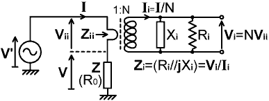
6.2-9. Insertion impedance and insertion loss: There is a little more to the design process that just considering the output voltage and frequency response because the transformer has an input impedance and therefore causes a voltage drop in the transmission-line into which it is inserted. The transformer also abstracts a certain amount of energy, and we need to consider what happens to the resulting heat. In order to calculate the insertion loss due to a current transformer, and hence the power rating of the secondary load, consider the circuit in the manner shown below: |
|
Using the definitions in the diagram, the input impedance or
'insertion impedance' of the primary is Zii=Vii/I. Now note that Vii=Vi/N and I=NIi.
Hence: Zii = (Vi / N ) / ( N Ii ) i.e.,
If the current transformer is used as part of a monitoring device in a power transmission system, then we can work out the operating insertion loss on the basis that the primary load impedance will be adjusted to be a pure resistance R0 (i.e., the transmitter cannot be turned-up to full power until this adjustment has been carried out). We may also observe that maximum energy will be absorbed when the reactance Xi is large in relation to the secondary load resistance Ri (i.e., in the middle of the passband); in which case the insertion impedance of the transformer will be predominantly resistive. Hence we can deduce the worst-case insertion loss on the basis of a nominal mid-band 'insertion resistance' Rii, where: Rii = Ri / N² The ratio of primary load voltage to generator voltage for the system depicted above is V/V', this being dictated by the potential divider network formed by Rii in series with R0, i.e., V / V' = V / ( Vii + V ) = I Rii / I ( Rii + R0 ) The primary current is eliminated giving: V / V' = Rii / ( Rii + R0 ) Hence the mid-band insertion loss in dB is:
The worst-case power dissipated in the secondary load resistance (i.e., assuming no losses in the transformer) is equal to |I|²Rii, i.e.,
Example 1: For a current transformer with 40 turns on the secondary, and a 50Ω secondary load, the nominal mid-band insertion resistance, (Ri/N²), is 0.03125Ω. This corresponds to an insertion loss of 0.005dB, i.e., -20Log[ 50/(50.03125) ], when the generator (transmitter) is working into a 50Ω load. If the generator is delivering 1.5KW, the primary current, √(P/R), is 5.48A. The secondary current is 5.48/40=137mA, and the secondary voltage is 0.137×50=6.85V RMS. The power dissipated in the secondary load resistor is 0.137×6.85=0.94W. The secondary load can therefore be constructed by placing two non-inductive 100Ω resistors of at least 0.5W power rating in parallel. Example 2: For a current transformer with 10 turns on the secondary and a 50Ω secondary load, the nominal insertion resistance is 50/10²=0.5Ω. This corresponds to a maximum (mid-band) insertion loss of -20Log(50/50.5)=0.09dB when the generator is working into a 50Ω load. If the generator is delivering 100W, the primary current is 1.414A, and the secondary current is 141.4mA. The secondary voltage is 0.1414×50=7.07V RMS, and the power dissipated in the secondary load resistor is 1W. |
|
© D W Knight 2008.
David Knight asserts the right to be recognised as the author of this work.
|
|
|
|
|
|
u