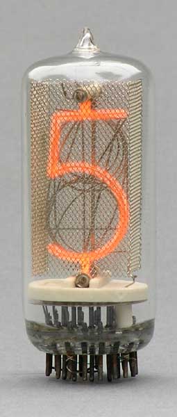
 |
Gas Discharge Tubes |
Counting tubes index page |
Coil Resonance Experiments |
Counting tube bulk gas illumination
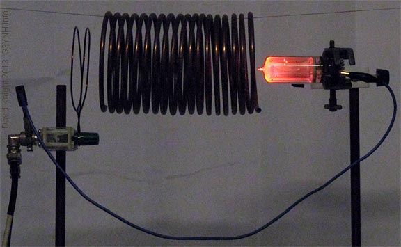
The bulk gas of a discharge tube can be made to ionise by subjecting the tube to a strong electric field such as occurs in the vicinity of a normal-mode helical antenna or a self-resonating coil. In lamps that are intended to be used as cathode-glow devices, the bulk discharge is usually supressed by using a short inter-electrode distance (so that the Crookes dark-space fills the tube). Thus RF excitation in this manner can give additional information about the fill gas.
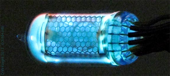
In the photograph above, a coil is excited at its self-resonance frequency by means of an induction loop driven using a radio transmitter (see coil resonance experiments). A weak glow in a nearby tube can be obtained without electrical connection, but earthing an internal electrode to the cable feeding the loop increases the field gradient and causes the whole tube to light brightly.
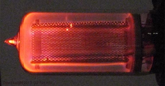
The tube shown above is a GR10G nixie. The anode pin is earthed, since this (the outer mesh cage) creates the greatest capacitance between the tube and the nearby coil.. The frequency is 24.7 MHz. A close-up of the tube is given below, with the normally-operating tube shown on the right for comparison.
|
 |
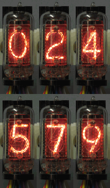 |
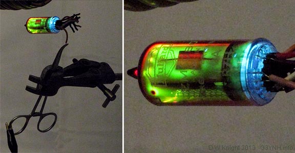
Above Right: Although the bulk gas glow appears cyan, the numeral display with 200V DC on the anode and a 33 kΩ series resistor is orange. The running voltage is ca. 140 V, and so the current in this case is 1.8 mA.
The reason for the extreme difference between the two discharges is that the RF-induced glow is essentially a positive column discharge (having the spectrum of an arc discharge even if the current density is low). In cathode-glow lamps, the positive discharge is not usually noticeable, due to the short inter-electrode distance, but it appears in the high-frequency bulk gas discharge because the electrodes are not involved and there is little overall ionic migration. With DC bias across the electrodes however, we see the cathode glow, and the positive column glow is practically eliminated. In this case, the positive column has the cyan colour characteristic of Hg vapour, whereas the cathode glow is characteristic of neon. Thus the fill gas is Ne, with a trace of Hg.
No cute furry animals were harmed . . . . .
The photographic animation sequence of the working XN12 on the right (above) was taken after the abuse depicted in the photograph on the left. Evidently the tube is unfazed by its ordeal (but it did get quite warm).
 |
Gas Discharge Tubes |
Counting tubes index page |
Coil Resonance Experiments |
© D. W. Knight, 2013
