 |

The Art of Discharge Tube making
by Peter Jameson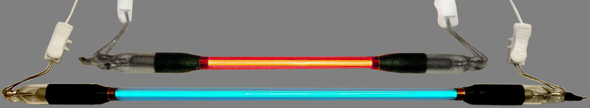
I suppose this glowing gas discharge lark started when I was at the tender age of 10. Someone in the family broke the top glass reservoir of the coffee maker. This left me with a lovely spherical glass vessel with a narrow neck, which had spent all it’s life hitherto as the bottom coffee receiver of the coffee maker. It was just like a piece of laboratory glassware as seen on TV science programmes for children.
Well, I’d already studied lots of neon negative glow lamps close up. I had several similar in shape to the well known pygmy tungsten lamp, and lots of miniature neon indicator lamps. Seeing that all they consisted of was two electrodes in a glass bulb and knowing that the neon gas inside was at low pressure, my newly acquired round bottomed flask was crying out to become a negative glow lamp.
I had rubber bungs, a bung borer, and a glass tap from a broken burette, which I’d assumed as part of a job lot from someone dismantling a laboratory and selling it off in the “Exchange and Mart”. So, armed with these items, I bored a bung to take the burette tap, forced two pieces of stiff wire through it, and placed it in the neck of my flask thereby adding my electrodes. There was my negative glow lamp. I evacuated it using the intake of the old ‘fridge compressor my father used as a tyre pump. Then I connected the mains in series with a fifteen watt bulb to the electrodes. I knew that current limiting would be needed, as I’d seen the resistors in series with my neon lamps, but these were early days for me and I had no proper resistors. The result: nothing. I did not understand why there was no electric blue air glow as I had not studied Paschen’s work; but concluded correctly that, for whatever reason, I needed more voltage. Out came my Parmeko 5kV 250mA boiler ignition transformer (how I survived childhood I’ll never fathom). There it was! The lovely blue negative glow of air at low pressure alternating around each electrode.
The project just about ended there save for my trying every type of gas I could get hold of, and there weren’t many. My brother brought me balloons full of argon and nitrogen from the engineering workshop, and I even tried coal gas from the gas main. Nothing was particularly impressive. Everything seemed to glow blue, due to my deuteranopia or perhaps due to air contamination, and neon was certainly out of the question because I couldn’t acquire it.
Quite a few years down life’s winding road, I got my first job as a lab assistant. At 20-something I had gained much experience and knowledge of matters scientific, and the lab work gave me access to lots of lovely glass artefacts from the broken glassware bin. Glass tubing, burette stopcocks, ready-made metal to glass seals from pH electrodes, etc.. In my mind's eye, I saw the possibility of resurrecting my initial experiments with electric discharge through gas.
Having acquired some fairly narrow glass tubing, I constructed a discharge tube using my wire through rubber bung technique and I included a burette tap in order to purge the tube and fill it with various gasses. Again, my father’s ‘fridge compressor-cum-tyre inflator was my vacuum pump. The results were impressive, and this gave me was my first observation of a phenomenon known as “beading” or “striations” or “jellybeaning” in the discharge column. A great puzzle. I had no real explanation for the phenomenon, and textbooks told me that it was due to discrete energy levels of the electrons passing through the tube. I realised that this was true for the various dark spaces in DC discharge columns, as documented by Faraday, Anson, and others, but that did not explain the complicated moving patterns I was seeing in AC discharge columns.
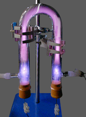
Early experiment with basic inexpensive equipment: The electrodes in the tube shown were made from Zn-plated gardening wire wound into a tight helix. The pressure was reduced, using a basic single-stage pump, until the discharge became visible. Vacuum control was by means of surgical forceps on the silicone tube. The U-tube was first purged with Argon. Then, with the pressure still at atmospheric, a potential was applied across the electrodes using a small CCFL inverter. No gauges were available at the time, but the pump could only reach about 5 torr, and the discharge tends to extinguish above 20 torr. Hence the pressure in the illuminated tube would have been in the 5 to 20 torr (0.67 to 2.67 kPa) range. |
Moving on some thirty years, and now in my very late middle years, I had left the scientific environment and taken a job as IT manager in a company that had a signage department (with a few other jobs in-between, naturally). We did not make neon signs, but we did supply them, with their having been made by a local manufacturer. This resulted in several neon signs being fired up on the bench before going out to the customer. One day a sign was lit-up, and “jellybeans” were seen travelling along the tube. The manager of the signage department was most upset and said that the sign would have to go back to the maker for regassing. When I asked what caused the phenomenon nobody knew, and I was asked if I had any ideas. I had not, so I ‘phoned the neon workshop and asked them. They did not know, but told me that it was pressure influenced and had become more common since the introduction of the electronic transformers. Two important clues there.
Skipping forward to the age of about 60, when of course I had plenty of the wherewithal, and with my retirement looming; I bought myself proper vacuum pumps, both roughing and diffusion, decent vacuum gauges, glass tubing, neon gas, argon gas and some Dumet wire. My initial hope was to make a simple negative glow lamp; by sealing two Dumet wires as electrodes into a simple tube, purging it with a neon/argon penning mixture and evacuating it with the current-limited mains across the electrodes. Success! Well, partly. Whenever I tried to seal a pinch off, I lost the discharge due to outgassing from the heated glass; which at the time I didn’t understand. That was my introduction to the importance of bombarding . . .
My next trick was to make a cold-cathode tubular positive column neon lamp. I’d learnt about bombarding from a local “neon” guy, and so had set up an high voltage transformer from an RF transmitter PA, with current limiting, as a bombarder.
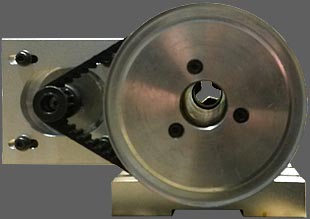
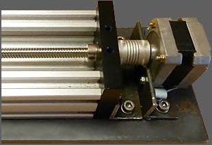
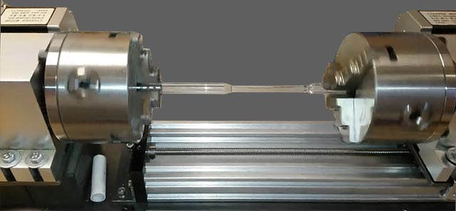
Since I did not have the relevant burners, or indeed the skill, I made a glass lathe from CNC chucks and stepper motors in order to rotate tubing and pre-formed electrodes at precisely the same speed. This allowed me to weld-on the electrodes at each end with an oxy-propane flame.
 |
 |
During the bombarding process, while my early tubes were still on the pump, I noticed that “beading” was closely linked to the pressure in the tube and it’s temperature too, but not current, so I concluded that the phenomenon might be due to acoustic resonance within the gas, synchronised to the 50 Hz mains frequency. Also, subsequently, I saw it change in sympathy with the frequency of a VFO powering an inverter which was operating the tube. The acoustic resonance idea might be investigated by arranging for a separate chamber to be added to the tube; the additional volume being allowed to communicate with the main gas column, or not, at the turn of a tap. Unfortunately, I do not have the glassworking equipment to achieve this.
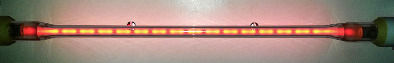
Beading in a discharge tube with a high-frequency AC supply (5 to 50 kHz region). The bright regions generally move, and are often smeared-out; but they can be made stationary by adjustment of the supply frequency. The appearance of beading in discharges is related to the gas pressure and temperature, and is possibly due to acoustic resonance.
After this long trek climbing mount impossible, with a bin full of dud tubes and broken glass, my tube making technique finally achieved perfection; and I’ve had a neon tube running continuously in my lab for around two years. I have also had the satisfaction of selling both neon and mercury tubes to scientifically-minded people and universities throughout the entire world.
Peter Jameson
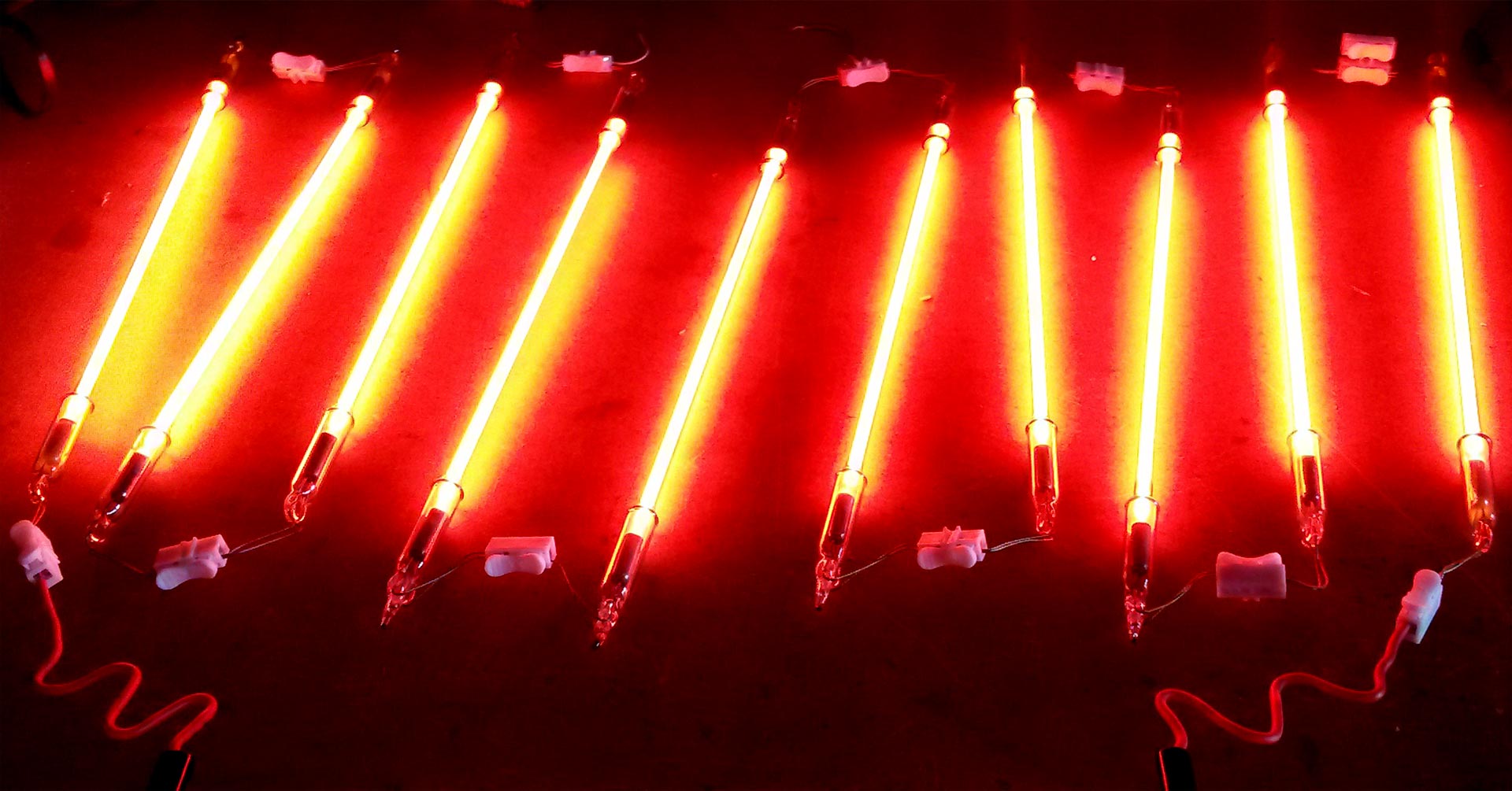
New Neon tubes in the process of ageing. This takes about 24 hours, during which time the Barium Oxide in the electrode shells getters-out reactive trace impurities such as N2, O2 and anything else that might have been accidentally included.
 Links:
Signindustry.com Online 'Neon' Self-Training manual:
Part 1: www.signindustry.com/neon/articles/2014-11-17-RCNeonSelfTraining.php3
Part 2: www.signindustry.com/neon/articles/2014-12-15-RCNeonSelfTraining2.php3
Part 3: www.signindustry.com/neon/articles/2002-05-31-RCNeonSelfTraining3.php3
Part 4: www.signindustry.com/neon/articles/2002-06-28-RCNeonSelfTraining4.php3
Bombarding is discussed in part 4. The target temperature is given as about 425°F. To convert Farenheit to °C, subtract 32 and divide by 1.8:
T/°C = ( T/°F - 32 ) / 1.8
This gives the target temperature as 218.3°C, i.e., about 220°C.
