| Glow-start Hg Vapour Lamps |  |
|
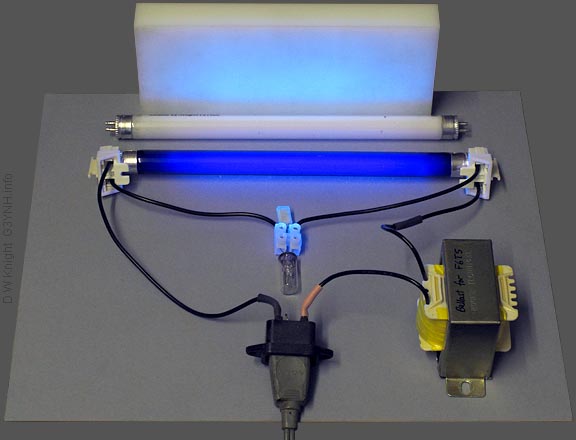
F6T5BLB 6 W blacklight (350 nm UV) tube. The tube shown operating above is a standard pre-heat (glow-start) striplight tube, containing about 5 mg of mercury and a noble gas (usually argon or krypton) to give a reasonably low striking voltage. It is electrically identical to the miniature F6T5 fluorescent tube. The difference is that the tube is made of a UV-A transmitting glass, and a coating has been applied to eliminate most of the visible light content. In a conventional fluorescent tube, the UV light from a low-pressure Hg discharge causes the white phosphor coating on the inside of the glass to fluoresce. Here, a conventional phosphor-coated tube has been placed next to the blacklight, as well as a block of Nylon 66. The UV light causes both the Nylon and the terminal block connecting the starter tube to fluoresce, but the phosphor gives little response. The reason is that the glass wall of the white lighting tube is a strong UV attenuator, protecting the user from the intense UV-C content of the un-filtered Hg emission. Note however, that a small amount of UV-A still passes through the glass, and this is generally regarded as deleterious to museum artifacts and art-gallery exhibits. For that reason, museum, gallery and archive keepers will often fit UV-absorbing (but otherwise transparent) sleeves over fluorescent tubes (see below), and sheets of UV-absorbing material over windows. The photograph above shows the standard electrical configuration for a mains-voltage Hg lamp. A cold-cathode discharge tube will generally require several kV to initiate a glow discharge, but it will then try to settle to an approximately constant inter-electrode voltage that depends on the composition of the gas mixture. The dissipation can then be controlled by placing a ballast resistance (in a DC circuit) or reactance (in an AC circuit) in series, to approximate a constant-current source. The problem with the Hg tube, for AC mains operation, is that it will not strike spontaneously. The striking voltage is lowered considerably by using a mixture of Hg vapour and a noble gas, but it still remains too high. The solution for general lighting applications (invented in the 1930s), is to place an oxide-coated thermionic filament source at each end of the tube, and pre-heat the filaments briefly at switch-on to produce some gas ions by electron bombardment. Pre-heating is generally controlled by an automatic starter switch, which closes momentarily to place the tube filaments in series with the ballast (see glow switches). Starting is also usually helped by a momentary voltage boost; which, in AC circuits, is obtained by using an inductor as ballast. The inductor provides a high-voltage pulse when the switch opens and the magnetic field in its core partially collapses. An avalance process then causes the ionisation to spread through the tube. Once the tube has struck, ion bombardment keeps the filaments hot enough to provide a supply of thermionic electrons. |
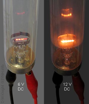 |
The internal workings of the glow-start tube can be seen through
the glass of a clear silica germicidal lamp. These lamps are
electrically identical to their phosphor-coated counterparts,
but the silica glass transmits the energetic UV-C radiation (particularly,
a strong component at 254 nm). Left, the oxide-coated thermionic glow cathode of an Osram HNS 30 W G13 (T8, 26mm diam., 0.9m long) tube has been connected to a laboratory DC power supply to light it up. 12 V (at 0.5 A) gives a brightness sufficient for tube starting. The metal ring around the filament is not connected to the tube base, and serves to reduce blackening of the glass by electrode evaporation (sputtering). |
| The silica (SiO2) envelope of the hard-UV tube is, incidentally, often referred to as "quartz". This is an old and widespread misconception (also perpetuated in the trade name of one very famous scientific equipment maker, and in the marketing of projector bulbs as "quartz-iodine" lamps). Quartz is crystalline silica (a piezoelectric constituent of granite). Silica glass (aka 'fused silica') is amorphous (disordered, non-piezoelectric) silica in the vitreous state. |
|
|
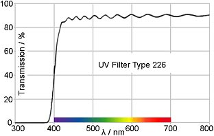 |
The transmission characteristic of the polyester type-226 Lee UV filter is shown on the left. The cutoff at around 400 nm is sharp, and the material is free from the gradual short-wavelength rolloff that imparts a yellowish tinge to the alternative Kodak Wratten 2 filter gel. |
| With a sleeve of Lee 226 material covering the HNS30W tube, there is no noticeable tendency for objects to fluoresce when illuminated by the filtered light output, nor any sign of skin burning after exposure (at least at the low intensity levels encountered during the experiments described here). In the photographs of the working tube below; a filter sleeve has been fitted and is held in place by pushing nitrile-rubber O-rings (Japanese S24 size) into the gaps between the tube end-caps and the sleeve. This creates a unit that is easy to handle (no danger of the tube slipping out of the sleeve), and suitable for use in lectures and demonstrations. |
|
To demonstrate the principal of operation of the tube, the author
used a low-voltage lab. variable DC supply for the heater, and
a 0 - 400 V variable DC PSU with a ballast resistor ( 2 × 2.2 kΩ 25 W) and a fluorescent lamp choke in series. The arrangement is shown in the diagram below. |
|
The DC resistance of the choke is negligible in this context,
but it allowed the glow discharge to be started by briefly shorting
across the tube terminals to generate a high-voltage pulse. Only
one end of the tube was heated; and that, of course, was used
as the cathode (-). The tube was started with 230√2 = 325
V across it, this being the peak value of the UK mains electricity
supply. The voltage was then turned down to reduce the current
to 15 mA, so that the tube could be photograped without overloading
the camera sensor. In the photographs below, the tube is shown first with the cathode heated, as necessary to get it to start, and then with the heating supply turned off. |
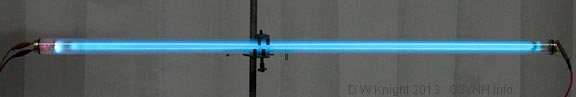
| Heater volts: 12 V ; Tube current: 15 mA DC ; Running voltage: 128 V (P = 1.9 W). |
|
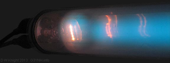
Heater volts: 0 ; Tube current: 15 mA DC ; Running voltage: 141
V (P = 2.1 W). Once the pre-heat phase has finished, thermionic emission is sustained by ion bombardment. This is indicated by the hot spot on the filament. The discharge around the cathode is known as the cathode glow. The gap between the cathode and the bulk glow is the Crookes Dark Space; which occurs because electrons emitted from the cathode have to be accelerated by the electric field for a while before they attain enough energy to ionise gas molecules. The glow after the Crookes space is called the negative column, and after that, the light output is reduced again in the 'Faraday dark space'. Following that is the positive column, which is also frequently striated. Dark spaces and other banding phenomena depend on the operating conditions. They occur because collisions release secondary electrons, which must be accelerated before they can ionise gas molecules further along the tube. In AC operation, the glow appears to fill almost the entire tube. This is because any gaps in the discharge when the tube is conducting in one direction tend to be filled in by the glow when the tube is conducting in the other direction. Banding with a low-frequency AC supply is not usually visible until the tube reaches the end of its life. What can happen then is that one of the cathodes loses all of its thermionic oxide coating before the other, and the tube only conducts significantly in one direction. Worn out tubes usually have blackened ends (despite the guard ring), due to electrode sputtering. They will still work to some extent as high-voltage cold-cathode tubes, but the sputtering process reduces the internal gas pressure due to gettering (the deposited material combines with the gas). Lowering the gas pressure increases the length of the Crookes dark space (which fills the entire tube in hard vacuum devices). |
|
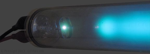
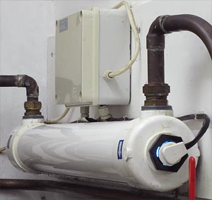
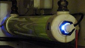
Right: With the room lighting switched off (and the camera ISO sensitivity turned up), the steriliser can be seen to emit a green fluorescence. This is due to the white filler pigment in the outer ABS housing material (probably identifying the filler as hydrated SiO2 - see Vaughn's summary). |
 |
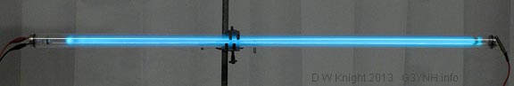
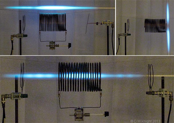
| Apart from its use as a model for demonstrating the principle of operation of the fluorescent striplight tube; the Hg-Ar germicidal tube (made safe by the addition of a UV-filter sleeve) provides an excellent way of demonstrating the electric field patterns that occur in the vicinity of radio antennas and resonating coils. Shown below are some exampless, which are discussed in detail in the article 'coil resonance experiments'. |
|
Lee 226 UV filter sleeving for striplight tubes: Fluorescent lamp circuits and info.: Hg lamp history and further information: |
|
|
|
|
|
© D. W. Knight, 2013