 |
|
|
|
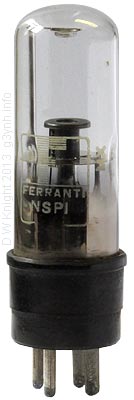
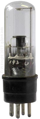
Neon Strobotrons
Ferranti NSP1
 |
 |
 |
 |
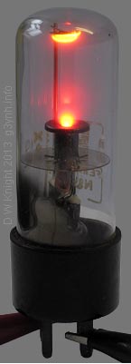 |
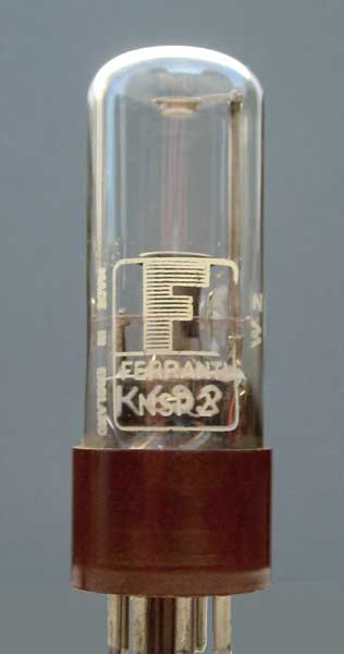
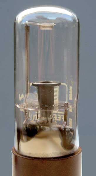
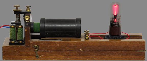
Above: Two
different NSP1 tubes. One marked MX externally and 193U internally on
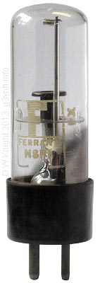
the pinch, the other marked PX externally and Y961 internally. Note that the wire to the top electrode is insulated by a length of glass tubing fitted over it, and passes through a mica sheet on its way to the glass pinch. Left: NSP1 connected to a high-frequency AC power source. The source was a single-transistor 6W fluorescent lamp inverter, designed to work from a 7.5 V DC supply but running on 3 V for the photograph to minimise overloading of the camera sensor. The appearance of the glow discharge suggests that the tube contains pure neon rather than a Penning mixture. Gas pressure is not given in the datasheet, but in the near-equivalent Sylvania 631-P1 (CV220) it is ca. 15 Torr (20 mBar). Note that the NSP1 is normally used as an arc tube. Unless carefully controlled, the higher voltage drop associated with glow discharges can result in excessive dissipation. Tube details: UX4 base. Electrically identical to NSP2 (Octal version). Datasheet . |
 |
 |
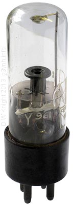
Ferranti
NSP2 (CV2296) Stroboscope tube with repetition rate up to 250 Hz. International Octal (B8U) base. Electrically identical to NSP1 Datasheet Photos on left: © Andy Cowley, M1EBV, 2005 |
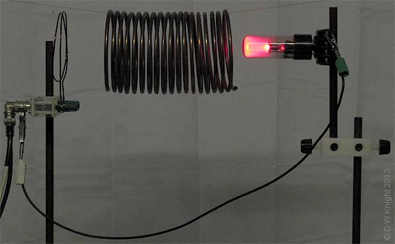
NSP2 with bulk gas ionisation due to the strong electric field of a coil self-resonating at about 25 MHz (for practical details, see: coil resonance experiments). The tube cathode pin is earthed to the cable feeding the RF induction coil. This causes the control electrode structure to glow due to ion-bombardment (prolonged operation in this manner is not recommended).
NSP2 powered by a Palmer induction coil. The Palmer coil produces HV pulses by interrupting the primary coil current (using a buzzer). The secondary coil is movable on a slide to allow the mutual inductance to be varied. Power supply to the interrupter in this case is 1.5 V DC.
Links:
| |
|
|
|
© D. W. Knight
2013, 2021
