| |
|
|
|
|
2. Components and Materials: Part 4.
Contents:
| 2-11. Capacitance, capacitors and
Insulators. 2-12. Measuring Permittivity. 2-13. Capacitor Impedance. |
2-14. Complex Permittivity. 2-15. Loss Tangent. |
| 2-11. Capacitance,
Capacitors and Insulators: Just as resistance and inductance are distributed throughout any electrical circuit, so too is capacitance. Most readers will of course be familiar with stray-capacitance: the spurious coupling that exists between adjacent conductors and components, and self-capacitance: such as that which appears in parallel with a coil and reduces its effective inductance. We manage these phenomena: in the first instance by screening and a preference for low impedances in signal circuits, and in the second instance by learning to live with it and including it in our mathematical models. In all instances however, capacitance, whether wanted or spurious, is mediated by insulating materials; and it is a knowledge of the properties of such materials that must inform good RF practice. In particular, in power transmission applications, we need to understand the heating effect that occurs when insulators are subjected to strong time-varying (i.e., alternating) electric fields; since it is this which plays a large part in determining whether or not our coils, capacitors, transformers, and transmission lines will go up in flames. A capacitor, as should be understood by now, is nothing like a pure capacitance. It is instead, a device in which capacitance is engineered to some particular value (in Farads), and resistance and inductance are minimised to a degree suitable for the intended application. The basic objective is realised, in prototype form at least, by mounting two conducting plates in close proximity, with an electrical insulator of some description in between. In the context of capacitance, and also in the context of electromagnetic energy transmission, an insulating material is known as a dielectric. The term 'dielectric' means roughly: "opposed to", or "doesn't need" electricity; the general definition being: 'some medium in which a constant electrostatic field can be maintained without involving an appreciable supply of energy from external sources' [25]. |
| The capacitance of a capacitor is proportional to the overlap area of the plates A, and inversely proportional to the plate separation h, provided that a uniform electric field exists between the plates. The constant of proportionality is called the permittivity of the dielectric [6], and is given the symbol ε (Greek lower case 'epsilon'). The defining equation for capacitance is therefore: |
 |
|
| 2-12. Measuring
Permittivity: The measurement of permittivity at audio and radio frequencies is accomplished by measuring the impedance of a test capacitor and then correcting for unwanted contributions. If the measurement is made using a simple pair of conducting plates however, it will be found that the perfect proportionality of equation (2-11.1) is not exactly obeyed. In fact, the equation is most accurate when the area A is large, and the separation h is small; the reason being due to the non-uniformity of the electric field at the edges of the plates (see illustration right). The field-lines external to the capacitor somewhat resemble those of a bar-magnet, and although their contribution to the capacitance is small, it is not zero [26]. |
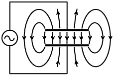 |
| Note incidentally, that some of the field-lines must extend to infinity, and so the capacitor must be small in relation to the wavelength at the excitation frequency if it is not to exhibit appreciable radiation resistance. Note also, that the conduction currents flowing into and out of the capacitor will be confined to the surfaces of the plates at radio frequencies. This means that currents will enter the region between the plates from the edges, and energy will flow in the capacitor in the same way that it travels in a transmission line. A wave flowing across the capacitor will find a discontinuity (open-circuit) as it reaches the edge and will be reflected. The result will be a pattern of standing waves and a non-uniform field distribution between the plates unless the capacitor is small in relation to the wavelength at the excitation frequency. |
| The solution to the edge-field (or fringing-field) problem when measuring permittivity is to encircle one of the capacitor plates with a guard-ring [10][18][25] (see right). During measurement, the guard-ring is maintained at the same potential (i.e., the same voltage) as the encircled plate, but forms no part of the measured capacitance. In this way, the fringing fields are associated only with the guard-ring, and the volume in which the capacitance is measured has a uniform electric field. The gap between the ring and the plate should be very small: a few percent of the capacitor spacing h; and the opposing plate should overlap the full area of the plate and guard-ring. |
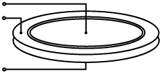 Guard-ring capacitor. |
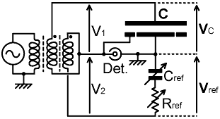
| The guard-ring can be maintained at the same potential as the associated capacitor plate by using a bridge circuit, one possible configuration being shown in the illustration below: |
 |
 |
| The arrangement shown is known as
a transformer ratio-arm bridge or TRAB, and makes
use of a bifilar-wound transformer to produce two voltages in series
(i.e., V1 and V2) that are exactly identical in
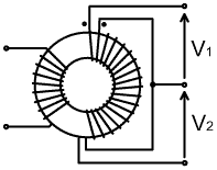
both magnitude and phase. A proper physical interpretation of the
transformer symbol is given on the right, the dots indicating the
points where the associated windings may be considered to start or
finish. Such a transformer is nowadays best constructed using a small
ferrite ring or 'toroid', with the excitation winding (the one
connected to the generator) spaced a little away from the bifilar pair
to prevent stray capacitance from upsetting the electrical symmetry.
The excitation source is an RF signal generator, and the detector
(connected to the port labelled "Det.") is typically a radio receiver
tuned to the generator frequency. In operation, the reference resistor Rref and the reference capacitor Cref are adjusted until the signal at
the detector is minimised; in which case the voltage across the test
capacitor (VC)
is identical in magnitude and phase to the voltage across the impedance
formed by Rref and Cref, (i.e., Vref) and the bridge is said to be
'balanced'. When the bridge is balanced, the impedance of the test
capacitor is exactly equal to Rref+jXCref, and since the voltage across
the detector is then effectively zero, the guard-ring is at exactly the
same electrical potential as the plate it encircles and any errors due
to fringing-fields are rendered negligible. A bridge measurement of course, requires a calibrated non-inductive non-capacitive variable resistor, and a calibrated non-resistive, non-inductive variable capacitor; neither of which are physically realisable. Extremely accurate measurements therefore require corrections for the imperfections of the reference components; i.e., we have to know the impedances of the reference components (and the connecting wires) at the test frequency, and we obtain the true reference impedance by adding these together. There also exists a correction formula, derived by Maxwell himself, for the very small non-uniformity of field which results from the gap between the earthed-plate and the guard-ring [25]. The uncorrected system however, while unlikely to impress the scientists who work for national standards bodies, is capable of engineering measurements, and will suffice to illustrate our point. See also: [Heerens & Vermeulen 1975, Capacitance of guard-ring capacitors . . .] [Moon & Sparks 1948, RP1935] |
| 2-13. Capacitor
Impedance: If a capacitor is perfect, the current that flows in and out of its terminals is exactly 90° out of phase with the applied voltage, i.e., the impedance of the capacitor is entirely imaginary. We cannot expect perfection however; and so the simplest capacitor model that we can use must consist of an ideal capacitor in series with a small amount of resistance. Such a model is shown below; where Res is the equivalent series resistance (ESR), and Ces is the effective capacitance when the impedance of the capacitor is expressed in series (R+jX) form. |
 |
Res
= equivalent series resistance (ESR) Ces = series-equivalent capacitance. |
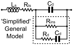
| This model is only applicable to a single frequency, because both Ces and Res vary with frequency. We expect the capacitance to vary of course, because there must be a magnetic field associated with any current flowing in the capacitor and its connecting wires; and the resulting inductive reactance must cancel some of the capacitive reactance, making the capacitance appear to increase as the frequency is increased. There will, incidentally, also be a resonant frequency, above which the capacitor will behave as an inductor; and so a single-frequency model that depicts the device as a capacitor is only applicable below the resonant frequency. We also expect a resistive component, part of it being attributable to the connecting wires and the metal plates, with a frequency variation due to the skin effect. When a material other than a vacuum is placed between the plates however, there is normally an increase in both the capacitance and the resistance, and these new elements have frequency (and temperature) dependencies of their own. To study dielectrics we must therefore separate these latter quantities from ordinary circuit effects, and in order to do so we will extend our capacitor model as shown below: |
 |
Ls
= series inductance Rts = 'true' (conductor) series resistance (TSR) C0 = capacitance 'without' dielectric. Rins = insulation leakage resistance Rd = dielectric losses Cd = additional capacitance due to the dielectric |
| The series inductance Ls is due to the plates and connecting
wires, and its inclusion in the model allows true capacitance to be
isolated by making measurements at several frequencies. Likewise, the
so-called 'true series resistance' is due to the plates and connecting
wires, and its contribution to the impedance at a particular frequency
can be determined by operating the capacitor without a dielectric
(i.e., with a vacuum dielectric, or some approximation to it such as
air). The capacitance in the absence of a dielectric is represented by C0; and the three components inside
the dotted box are the properties that only appear when a dielectric
is present. Rins is the
insulation leakage resistance, Rd
is the dielectric loss, and Cd
is the additional capacitance of the dielectric. The model is called a
'simplified' general model because it lacks physical realism in several
important respects: the main ones being that it does not include any
transmission-line effects, and the reactance of the dielectric cannot
be represented as a single series R-C combination (Rd+jXCd); but requires, in principle (but
fortunately not always in practice) an LCR network for every single
mechanical, atomic, and molecular process that can occur within the
material. This story will unfold in the discussion to follow; but we
will first familiarise ourselves with this basic model and its
relationship to the single-frequency model given earlier. The insulation leakage resistance, Rins, arises from the fact that no insulator (excepting vacuum) is completely perfect. It is not strictly a dielectric process because it relates to electrical conduction; but it is usually lumped into the dielectric losses because the effort of trying to separate it is neither worthwhile nor theoretically necessary. The types of insulators used in (properly designed) radio and electrical installations have resistivities in the range 1010 - 1019 Ωm (compared to a few tens of nΩm for conductors), and so, provided that we keep our equipment clean and dry, Rins is likely to be too large to make a measurable contribution to the system losses. A sample of polyethylene (polythene), for example, might have a resistivity of about 1016 Ωm. If we clamp a 1 mm thick sheet of this material between the plates of a test capacitor having an overlap area of 0.01 m² (112.8 mm diameter), the leakage resistance (assuming that the plates make good contact) will be: Rins = ρh/A = 1016 ×10-3 / 0.01 = 1015 Ω = 1000 TΩ In practice, the plates will not make good contact, and the resistivities of such awkward substances have to be measured by vacuum deposition of metal electrodes directly onto the material surfaces. In general, the only non-defective capacitors for which leakage resistance can be measured using commonplace test equipment are electrolytic capacitors. The diagram below shows a notional transformation, which takes us from the simplified general model to the series equivalent model from which the impedance of the capacitor is derived: |
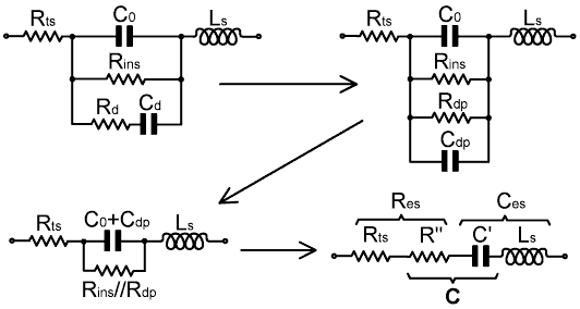
| The point of this illustration is to show that all of the translations between models are obtained purely by application of the series-parallel and parallel-series transformations described in [AC Theory, Sections 18 and 19]. We do not necessarily have cause to carry out such transformations explicitly, but it is important to understand that all of the models are equivalent at a particular frequency. In this case, we end up with the equivalent series resistance (ESR) of the capacitor, Res, being split into the true (conductor) series resistance Rts, and a dielectric loss component R" ("R double prime"). Similarly, the series-equivalent capacitance Ces is split into the circuit inductance Ls and a real capacitance C' ("C prime"). The reactance of the network will be capacitive provided that -XC' is always larger than XLs, a situation we must arrange if we want to persist in calling the device a capacitor. Now the important part: notice that if the dielectric is removed, Rins, Rd, and Cd in the initial model all disappear; and if we compare what is left to the final model, we see that the series combination R" and C' in the final model replaces C0 when a dielectric is inserted. Hence the network consisting of R" in series C' is the true capacitance C; and capacitance, as was mentioned previously, is in general complex. |
| 2-14. Complex
permittivity: The general capacitance equation was given earlier as: C = ε A / h = ε0 εr A / h We know that if the dielectric is removed, we obtain a capacitance: C0 = ε0 A / h but when a dielectric filling is inserted, C must be represented as a network consisting of a resisance in series with a capacitance. Since capacitance is also defined in terms of impedance; the only way in which we can force the definition of capacitance to be true in general is by assuming that permittivity contains an element that acts at +90° relative to the -90° of a pure capacitive reactance; i.e., permittivity has an element that gives rise to a resistive (0°) component in the capacitor's impedance. This, of course, requires that permittivity is complex, and it is customary to write it as: ε = ε' -jε" (the choice of sign is that which makes the resulting resistive component positive). Now, since vacuum capacitors do not have dielectric losses (i.e., ε0 is real), we can further identify the dielectric constant εr as the complex entity, i.e.: ε = ε0 εr = ε0 ( εr' -jεr" ) Hence:
|εr| = √[(εr')² + (εr")²] We are now in a position to write the expression for the true reactance of a capacitor (i.e., the reactance after correction for the circuit elements Ls and Rts) as: XC = -1/( 2πf C ) = -1/[ 2πf ε0 ( εr' -jεr" )( A / h ) ] but note that the term ε0A/h is just the capacitance of the capacitor without a material dielectric, i.e., it is C0, hence: XC = -1/[ 2πf C0 ( εr' -jεr" ) ] and -1/(2πf C0) is XC0, hence: XC = XC0 / ( εr' -jεr" ) Now, to make the denominator real, so that we may separate the reactance into its real and imaginary parts; we multiply the numerator and the denominator by the complex conjugate of the denominator, i.e.: XC = XC0 ( εr' + jεr" ) / [( εr' -jεr" )( εr' + jεr" )] hence, bearing in mind that j²=-1: XC = XC0 ( εr' + jεr" ) / [(εr')² + (εr")²] As is always the case when this operation is performed, the new denominator is just the square of the magnitude of the original complex denominator, i.e., in this case, [(εr')²+(εr")²]=|εr|², hence:
ZC = jXC = jXC0 ( εr' + jεr" ) / |εr|² = XC0 ( -εr" + jεr' ) / |εr|² Now recall that we expressed the true capacitance as a network consisting of a capacitance C' in series with a resistance R". Hence:
|
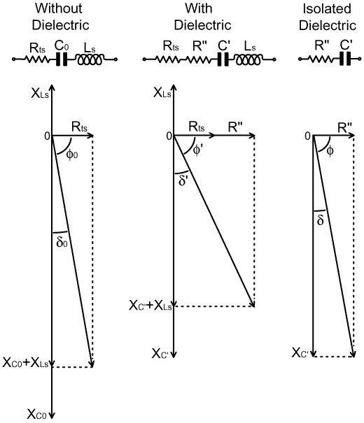
| 2-15. Loss Tangent: Shown below is a set of phasor diagrams that summarises our deconstruction of the capacitor model so far. The loss resistances in each case are considerably exaggerated for the purpose of clarity. |
|
For the capacitor without a material dielectric, the
true
capacitance C0 can, in
principle, be obtained from the capacitor dimensions. It is then
possible to obtain the series inductance Ls
from the discrepancy between the observed and the theoretical
reactance, and the conductor resistance Rts
from the real part of the impedance. Measurements must be made at
several frequencies and compiled into a graph of corrections for the
test setup because both Ls
and Rts vary with frequency.
Strictly, for this characterisation, the capacitor should be operated
in a vacuum; but the dielectric constant of air is well known
(εr' = 1.0005361
at 1bar and 20°C [8])
and its losses are extremely small (i.e., we can usually assume that
εr" =0), and so a
correction for the air can easily be applied. If extremely accurate
measurements are to be made, the reference air should be dry; i.e., the
capacitor should be operated in a closed vessel in the presence of a
desiccant such as silica-gel, the dielectric constant of air at
20°C rising to 1.00066 for 60% relative humidity [8a]. For
engineering purposes however, knowledge of relative permittivity to
three decimal places is usually adequate, in which case, ordinary room
air can be assumed to have εr'=1.0007. For a complete capacitor
|
| For an insulator Tanδ = -R" / XC' Now recall that we have already derived expressions for R" and XC' in terms of the complex permittivity (equations 2-14.1): These are: XC'=XC0εr'/(|εr|²) and R"=-XC0εr"/(|εr|²). Hence:
In modern technical literature, dielectric properties are usually stated in terms of εr' and Tanδ. If, for any reason, εr" is required, it can be obtained from equation (2-15.1) above, i.e.:
Tanδ = Tan[ Arcsin(PF) ] The result should be rounded to the same number of decimal places as was given for the power factor. In books and papers not adhering to the complex permittivity convention, "dielectric constant", "k", or "specific inductive capacity" is equivalent to εr'. In general, for use in the presence of strong RF fields, a dielectric should be considered to be acceptable only if it produces a loss angle of substantially less than 1°, i.e., a phase angle between 89 and 90°. Tanδ=0.01 corresponds to δ=0.57°, and so is a figure to bear in mind as a reasonable upper limit for suitability. Properties of various dielectrics are listed later in this chapter; but before we examine the technical data we will arm ourselves for the purpose of interpreting it by taking a look at the processes that occur inside dielectric materials. |
© D W Knight 2007.
Last edited: 2019-May-26
David Knight asserts the right to be recognised as the author of this work.
| |
|
|
|
|