|
|
|
|
|
|
Inductors with Magnetic Cores.
|
Introduction: >>>> not yet written >>>> Below is a draft for a basic introduction to the subject. |
|
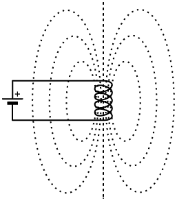
1. Magnetic circuits: When an electric current flows in a wire, a magnetic field appears around the wire. If the wire is wound into a helix, the fields associated with the individual turns add together to form the well known pattern associated with a bar-magnet. The curved lines of the field represent so-called lines of magnetic flux, 'flux' being an old-fashioned word meaning 'flow'. Thus, in a sense, a current of magnetism is considered to flow out of one end of the coil and loop around in the surrounding space before flowing back into the other end. This does not really happen; i.e., there are no particles of magnetism that we can capture as they emerge from the coil; the flux-concept is an analogy, but it is 'true' in the sense that it correctly describes the behaviour of magnetic devices. |
 |
| If a bar of ferromagnetic material, such as iron, nickel, or cobalt, is inserted into the coil, the lines of magnetic flux tend to concentrate within the bar. Thus the magnetic field strength within the region of space occupied by the bar is increased, even though the magnetising force due to the current flowing in the coil remains the same. It can therefore be said that magnetism prefers to 'flow' in materials of high relative magnetic permeability (or just plain 'permeability' for short). Magnetic permeability is given the symbol μ (Greek lower-case 'mu'). Because the bar is only on the inside of the coil however, the lines of flux must emerge from the ends of the bar so that they can loop around outside the coil to complete their circuit, and so the bar behaves as a magnet. |
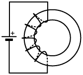
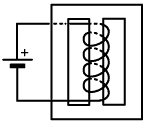
| If the magnetic material is fashioned in such a way that it provides a path for magnetic flux on both the inside and the outside of the coil, then the coil ceases to function as an electromagnet. The reason is that the flux can now complete its circuit in a highly permeable medium, and as with all things in nature, it is inclined to take the path of least resistance (or in the language of magnetic theory, the path of least reluctance). Thus a ferromagnetic ring or 'torus', or a double-aperture core (see right), is said to close the magnetic circuit, thereby confining the magnetic field tightly within the vicinity of the coil. The confinement can never be complete however, because even a vacuum has some magnetic permeability, and even the most permeable of iron alloys is not infinitely permeable. Thus some of the magnetic flux, the leakage flux, escapes from the core, and although the amount is often very small, we are not always in a position to neglect it. |
  |
| The amount of leakage flux depends on the length of the artificial magnetic circuit, the cross-sectional area of the magnetic 'pipe' through which the flux is channeled, the intimacy (tightness) with which the winding is associated with the core, and of course the relative permeability of the magnetic material. The latter is a particular issue in the design of radio-frequency magnetic devices because, as we will see shortly, core materials for inductors (as opposed to those for DC electro-magnets) must not conduct electricity, and so the magnetic particles must be dispersed in a block of insulating material. Thus the cores for radio-frequency coils (and indeed all coils for all AC circuits) involve a compromise between permeability and conductivity, and the popular idea that toroidal coils have no leakage flux is a myth. |
|
2. Inductance Factor:
Every commercially-manufactured closed-magnetic-circuit inductor core, of reasonably high permeability (μ≥10), has a good AL value associated with it (Open-circuit cores also have AL values, but these are much less reliable). The units of AL are Henrys per number of turns squared, i.e., H/turn²; although some manufacturers adopt the unfortunate practice of quoting it per 100 turns² or per 1000 turns². Conversion of the AL value into its proper and least-confusing form is accomplished by dividing the value in Henrys per N turns² by N². For example; The Amidon T50-3 toroidal core has a quoted AL value of 175 μH/100 turns²; dividing by 100² gives AL=17.5 nH/turn². 12 turns of wire on this core has an inductance of 17.5×10-9×144 H, i.e., 2.52 μH. The Amidon FT50-43 toroid has a stated AL value of 523 mH/1000 turns² (it is doubtful that anyone would ever have reason to wind 1000 turns of wire onto one of these cores); dividing by 1000² gives AL=523 nH/turn². 8 turns of wire on this core gives L=523×10-9×64 H = 33.5 μH. The tolerance of inductances calculated using AL values incidentally, should be taken to be about ±25% in the absence of other information, the worst accuracy for a given core geometry being associated low-permeability materials. Note also, that some texts give the units of AL as Henrys (or sub-multiples thereof), the logic being that the number of turns is a dimensionless quantity and therefore need not be stated. Here we will generally prefer to include the redundant " /turn² ", because the stated unit of measurement then embodies the formula for working out the inductance, i.e., multiplying a quantity stated in H//turn² by the square of the number of turns used gives a quantity in Henries. Initial Permeability: The inductance factor for a magnetic core can, of course, be obtained by winding a few (10 - 20) turns of wire on it and measuring the inductance, using the relationship:
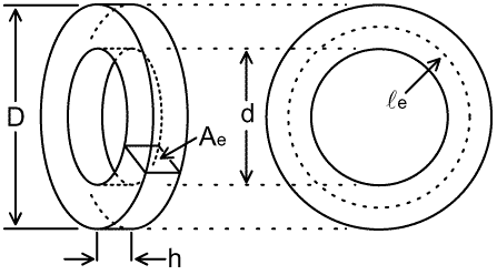
From this, it is possible to calculate the approximate permeability of the magnetic material used; and this may be helpful in identifying and characterising cores. The procedure involves estimating the effective area, Ae, and the effective length, le, of the magnetic path, as shown for a toroid in the diagram below: |
|
The effective path-length is roughly equal to the average circumference
of the ring, i.e.: le ≈ π (D + d) / 2 This formula is only approximate because the effective radius should strictly be chosen as the distance to a point on the path where the magnetic flux on the outside is equal to the magnetic flux on the inside. The problem of finding the true effective radius is entirely analogous to the problem of finding the effective current-sheet radius of a solenoid coil, as discussed in TA3.1 (see "homogeneous rectangular conductor", section 2, up to equation 2.1) >>>>>> The derivation of the exact formula should go here. >>>>>> The effective path area is: Ae ≈ h (D - d) / 2 Note that the Ae value is approximate because magnetic toroids usually have rounded edges to prevent damage to the enamel insulation on the winding wire. There may also be a discrepancy due to the thickness of any coating or paint. Consequently, the Ae value estimated from physical dimensions may be slightly optimistic. If the AL value is obtained from an inductance measurement made using a low voltage per turn (i.e. low flux density in the core), then the value of permeability determined is called the initial permeability μi. AL is also usually measured at a relatively low-frequency (<100 kHz for radio cores) in order to avoid dispersion effects (see later). Low-frequency measurement also reduces the effect of stray capacitance and coil self-capacitance, which cancels some of the inductance and leads to false readings at high frequencies. Relative permeability is then given by the expression below, with the subscript 'i' indicating the low flux-density, low-frequency measurement conditions:
μ0 is the permeability of free space and has units of Henrys/metre. AL is the inductance of a 1-turn coil in Henrys. le is in metres, and Ae is in metres². Note that the units of μi are H×m/[(H/m)×m²], all of which cancel to leave unity; i.e., relative permeability is dimensionless. Example: The Amidon T50-2 core has an inductance factor of 4.9 nH/turn² and the nominal value for μi is 10. The table below shows the physical dimensions taken from the data sheet compared to measurements made on a single sample using an engineer's vernier caliper. |
|
|
|
|
/mm |
|
|
|
(calculated) |
| Published |
|
|
|
|
|
|
|
| Measured |
|
|
|
|
|
|
|
| Note that when calculating μi using the equation above, it is necessary to multiply the path-length in mm by 10-3 to convert it into metres, and to multiply the area in mm² by 10-6 to convert it into m². Observe also that the measured Ae in this example is larger than the published value due to the neglect of edge-rounding, but that it is offset in this case by the estimated le being longer than the published value. Had this been an unknown core, we would have had no dificulty in identifying it as a material of nominal μi=10. Positive identification in this case is assisted because Micrometals type-2 cores are painted red. |
|
Core Materials: A magnetic core increases the inductance of a coil by an amount roughly proportional to the effective (relative) permeability of the core material μeff. For an open-circuit core such as a ferrite-rod or a threaded adjustment-slug, the effective permeability is very much lower than the permeability of the material itself because most of the magnetic path is in air; but for closed core such as a toroid, μeff is very nearly equal to μ. One of the advantages of a core, is that it reduces the amount of wire needed for a given amount of inductance, and so reduces the resistance of the coil. This means that a core has the potential to increase the Q of the coil, but this advantage will not necessarily be realised on account of losses in the core, which give rise to a resistive component in the impedance of the coil and so reduce the Q. Core losses arise from two causes, one being hysterisis, and the other being eddy-currents. Hysterisis loss is the energy required to reverse the magnetisation of the magnetic domains in the core. Eddy current losses are due to the transformer effect, which induces circulating electrical currents in the (resistive) core material. At low frequencies (power-line and audio), eddy current losses can be made negligible by laminating the core, i.e., constructing it from sheets of iron-alloy separated by thin layers of insulation. As the frequency is increased however, either the scale on which the loop-currents can occur must be made smaller and smaller, or the resistance of the eddy-current paths must be made very high. Cores for RF applications are therefore either made from finely-powdered iron in an insulating binder, or from ferrite materials, which are high-resistivity magnetic ceramics. For radio-frequency applications, ferromagnetic core materials can be divided into four classes: carbonyl iron powder, hydrogen-reduced iron powder, Nickel-Zinc (Ni-Zn) ferrites, and Manganese-Zinc (Mn-Zn) ferrites; all of which can be varied in composition to establish a desired degree of permeability. In general, powdered iron cores have the lowest permeabilities, and Mn-Zn cores the highest, but the available permeability ranges overlap. High-permeability materials have the highest losses at high frequencies, and are most susceptable to magnetic saturation. Permeability ranges and areas of application are summarised in the table below: |
|
|
|
Applications. |
| Carbonyl Iron |
|
High-Q inductors. Broadband transformers. |
| H-reduced iron |
|
Interference suppression. LF chokes. SMPS filters. |
| Ni-Zn Ferrite |
|
High-Q inductors. Broadband Transformers. VHF ferrite-rod antennas. |
| Mn-Zn Ferrite |
|
SMPS. Interference suppression. MF ferrite-rod antennas. Audio chokes (loudspeaker crossover neworks). |
| The fact that there is considerable overlap between the permeability ranges, and little to distinguish the materials visually in the absence of colour codes (which depend on the manufacturer), should act as a warning to those who buy undocumented magnetic cores. Full characterisation of materials for a particular application requires testing at several frequencies and flux-levels, and for those who lack the necessary test-equipment, it is probably better to purchase new cores according to advice in the data-books than to salvage old ones. The high-frequency performance of ferrites is limited by resistivity (eddy-current losses), and the Ni-Zn ferrite give best results in this respect. The high-frequency performance of powdered-iron cores is limited by particle size, for similar reasons, and the carbonyl-iron types give best results. |
|
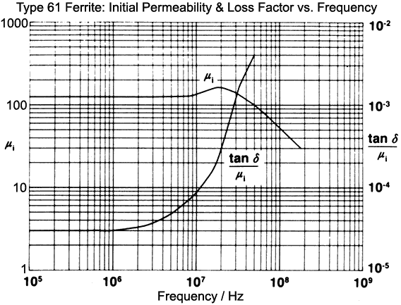
Dispersion and complex permittivity: The permeability of magnetic materials is analogous to the permittivity of dielectric materials; which means that permeability is strictly complex and has its real and imaginary parts related in the same way that the real and imaginary parts of the dielectric constant are governed by the Kramers-Kronig relations. Hence we expect a series of dispersion regions in the relationship between permeability and frequency; i.e., there will be frequency ranges in which a peak in core losses is associated with change in the real part of permeability. In the latter case, as frequency increases, there may be a gentle reduction, or an initial increase followed by a steep reduction; just as there is in the permittivity of electrical insulators. The difference between magnetic materials and dielectrics however, is that, in radio-frequency practice at least; it is almost impossible to avoid operating a magnetic material either in the wings of or actually within one of its dispersion regions. Hence core loss cannot be neglected with impunity, and the AL value of a core can be expected to vary with frequency. The graph below shows the dispersive behaviour of Amidon (Fair-Rite) type 61 Ni-Zn ferrite material, where the imaginary (loss) part of the permeability is given as Tanδ/μi. |
|
Flux-Density and Saturation: A ferromagnetic core increases the inductance of a coil because it allows energy to be stored by alignment of magnetic domains within the material. As the strength of the magnetic field increases however, there will come a point when all of the domains that can be aligned are aligned, after which, no more energy can be stored in this way. |
|
V = 2πf N A B / √2 = 4.4429 f N A B >>>>> unfinished Define hard and soft Ferite 2000 gauss (0.2T) Fe powder - 5000 gauss (0.5T) Power rating and temperature rise. Curie point. Annealing. Permanent damage. Cores permit miniaturisation, but this requires consideration of power dissipation. Air gaps. Effect of DC (smalll DC - diode det, mast-head relay, etc, ok) Thermal stability Pros and cons: Ferro cores: self-shielding. Miniaturisation. Coupling factor. Air cores: Linearity. . |
© D W Knight 2008.
David Knight asserts the right to be recognised as the author of this work.
|
|
|
|
|
|