 |
TX to Ae | Magnetics | Discharge Tubes |
Inductively coupled devices
Electromagnetic Induction.
The relationship between the physics and the small-signal electrical behaviour of transformers
By David W Knight.
Overview:
This article introduces the theory required for the analysis and modelling of inductively-coupled networks. The material presented is applicable to electrical transformers of all types, but the examples given relate primarily to high-frequency signal-processing applications. Familiarity with circuit analysis technique is assumed; but magnetism is discussed at an elementary level in order to ensure that the fundamental concepts are understood.
 Familiarity
with the basic
properties of ideal transformers is here assumed. A brief introduction
is given in AC Theory, section 41.
Familiarity
with the basic
properties of ideal transformers is here assumed. A brief introduction
is given in AC Theory, section 41.
Current transformers
are discussed in the RF
bridges section.
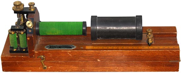
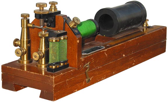
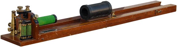
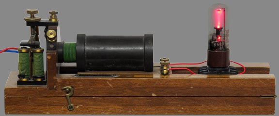
Palmer Mutual Inductance Apparatus.
Intended for use as a teaching laboratory demonstration. Made by C. F. Palmer Ltd., (Charles Fielding Palmer) Effra Road, London S.W.2. Probably ca. 1950 (no date marking). Distance scale is in cm. Screw threads are BA.
Despite the Victorian appearance, the use of plasticised PVC sleeving (on the buzzer coil leads) indicates that manufacture of this particular coil cannot have taken place until some time after the invention of PVC (1926). PVC started to come into widespread use in the late 1940s.
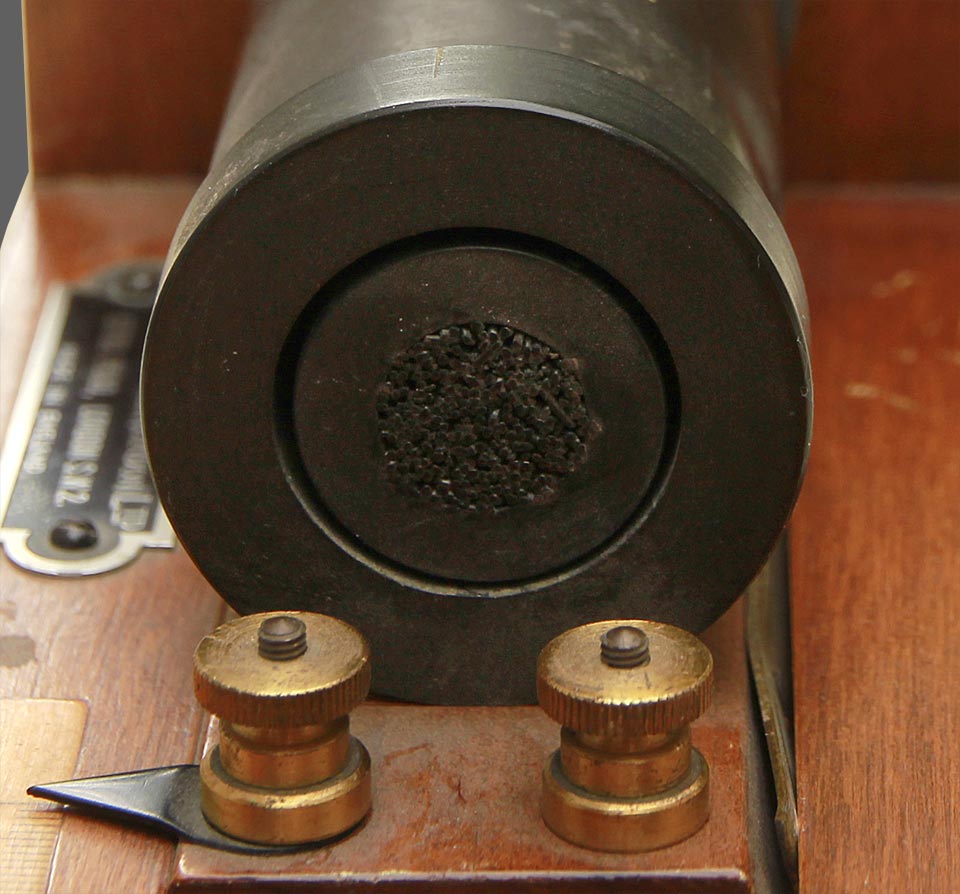
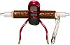
The primary of the Palmer Induction
coil (and other Ruhmkorff-type coils in general) is packed with lengths
of varmished iron wide disposed in the axial direction (see right). The
varnish insulation increases efficiency by preventing eddy currents
from flowing in the radial (winding) direction.
Click the picture to
enlarge
Tinsley Precision Variable Mutual Inductor
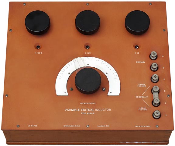
Variometer using stranded silk-covered wire wound on marble formers. Secondary is centre-tapped to enable use in Heaviside-Campbell and Carey-Foster bridges.
Features very low capacitance between secondary windings to give negligible capacitance error, resulting in high accuracy. Consists of a primary coil and three secondary coils having mutual inductances with the primary of 1, 3, and 6 units. Other values are given by +ve and -ve combinations of the three basic units. Eg., 2 is given by 3-1, 5 by 6-1, and 10 by 1+3+6. These combinations are given by a special type of 6-pole dual contact switch. In this way, a variable mutual inductance standard is built up.
Info originally obtained from the Tinsley 2002 catalogue / Product Range / Specialist Standards Equipment.
Top panel demensions are 42 cm × 36 cm. Overall height: 159 mm. Weight: 15.6 kg.
Widely used in magnetic susceptometry.
© D W Knight 2009 - 2013 - 2021.
David Knight asserts the right to be recognised as the author of this work.
| |
-
|