|
 |
|
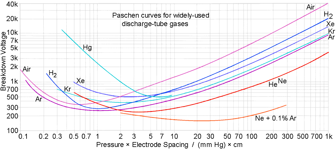
A gas discharge tube is a bulb or tube (usually glass), with two (or more) electrodes inserted into it, that has been evacuated and filled with a gas or gas mixture usually at somewhat less than atmospheric pressure. All such tubes have the property that, as the voltage applied across the electrodes is increased, there comes a point called the 'strike voltage' or 'breakdown voltage', at which any localised ionisation of the gas will initiate an avalanche process that spreads through the tube. The voltage at which breakdown occurs depends on the composition and pressure of the gas mixture and the strength of the applied electric field according to a relationship known as 'Paschen's law'. Somewhat surprisingly, the breakdown voltage does not simply increase with electrode spacing, but follows a bathtub curve, i.e., there is a range of spacings for which the breakdown voltage actually increases as the electrodes get closer together. The reason for that is that breakdown depends on the probability of collisions between electrons and atoms, and there is a regime in which shortening the inter-electrode distance makes the collision probability too low to initiate the avalanche process.
The Paschen curves for some of the common discharge-tube gases are shown below. These curves assume flat parallel electrodes of diameter comparable to or less than the length of the tube.

To give an idea of how to interpret the graph, note that atmospheric pressure is 760 mm Hg (760 Torr, 101.325 kPa, 1.01325 bar). Therefore a vertical line corresponding to 76 on the pressure × distance axis above gives the breakdown voltage for a gas between a pair of flat electrodes separated by 1 mm. For air, this gives a breakdown voltage of about 5 kV DC (3.5 kV RMS AC). Thus the air curve can (for example) be used for working-out the voltage ratings of air variable capacitors; although a safety margin is normally included to allow for surface roughness and sharp edges, which can reduce the breakdown voltage considerably.
Electrodes, incidentally, are not essential for gas breakdown. Any method that produces a strong-enough electric field, with or without electrodes, will also cause the gas (or regions therein) to glow; which is why discharge tubes light up when placed near resonant radio antennas and coils.
Once a glow discharge between electrodes has initiated; a low resistance current-path is formed, and passing a current sustains the discharge. Thus the tube resistance remains low, and the glow will continue, until the current falls below a value called the 'extinction point'. The voltage at the extinction point is usually considerably lower than the strike voltage, i.e., the discharge is difficult to get going, and then difficult to stop once started.
A gas discharge tube, once it has struck, usually has a negative resistance characteristic. This means that the product of the voltage across the tube and the current through it diminishes as the current is increased. Thus the current is effectively unlimited, and must be controlled by the external circuitry if it is not to lead to the destruction of the tube or the power supply. Some tubes are intended to be operated in a range where the voltage remains almost constant as the current increases (the glow-discharge region). One such application is as a voltage regulator, the current being limited by a series resistor in much the same way as for a Zener diode. Tubes can also be designed to work in a range where the voltage falls as the current increases (the arc discharge region), and while this is often an incidental feature, such tubes can be used to make oscillators that work in the same way as the tunnel diode (Esaki diode) oscillator. Note that, for tubes in which the running voltage increases as the current is reduced, the extinction voltage is higher than the lowest running voltage.
Since the tube running voltage is considerably lower than the strike voltage, tubes with an applied voltage above the running voltage but below the strike voltage can be triggered. This can occur in various ways, such as by illumination of the cathode by ionising radiation, passage of radioactive particles through the gas, or by the use of a triggering electrode.
When used as continuous light sources, discharge tubes are operated using something approximating a constant-current source. In DC circuits, this can be a ballast resistor in series with a high voltage source, or some kind of high-voltage inverter designed to have a high effective internal resistance (but without the losses associated with an actual resistor). In AC circuits at power-line frequencies, the reactance of an inductor can be used to limit the current, but additional complexity arises from the need to get the tube to strike and to keep it running during polarity reversals. The original solution, as used for neon signs before the advent of electronic inverters, was to use a high-voltage step-up transformer deliberately constructed to have a very large leakage inductance (a magnetic-shunt transformer). Such a transformer is equivalent to a an AC voltage source with a large series inductance (but requires only a single iron core).
| Lighting tubes often have oxide-coated thermionic cathodes, to reduce the running voltage by enhancing the supply of free-electrons. Such cathodes are usually heated by ion bombardment rather than by passing a current through a resistive filament. Pre-heating of the cathode at switch-on however is a convenient way of getting the tube to start. |
Another way to obtain white light is to use the ultraviolet light from a low-pressure gas discharge to cause phosphors to fluoresce. This, of course, is the principle of operation of the ubiquitous fluorescent tube, which produces UV light using a mixture of mercury vapour and argon.
Discharge tubes are often provided with a third electrode (and sometimes a fourth). There are two main reasons for doing so: priming and triggering. A priming electrode is generally an additional anode or cathode connected to a bias supply and disposed in such a way as to make it easier to get the tube to strike. Often, in DC circuits, the priming electrode is used to maintain a small reservoir of ionised gas (it is a sort-of pilot light). This solves the problem that, if the maximum available voltage barely matches the strike voltage, and the ambient background radioactivity is low (not an entirely undesirable situation), and the tube is in total darkness, there may be a waiting time of several seconds (and in some cases, minutes) before the tube will strike.
As an alternative to a priming electrode, a small amount of radioactive material can be placed inside the bulb [see link below]. Radioactive gases such as tritium (H3) are often used, but the material can also be in the form of a loose powder or some other solid mineral inclusion. Alpha emitters are best for this purpose, since α-particles (helium nuclei) cannot escape beyond the glass wall. Because of the container shielding effect, the use of radioactive material is not necessarily detectable from outside the bulb.
When a triggering electrode is included, the tube is known as a 'thyratron' and can be used as a controlled switch. The name of the solid state equivalent, the 'thyristor' (aka 'silicon-controlled-rectifier') is coined from the combination 'thyratron-transistor'. Thyratrons are made in cold-cathode and heated cathode versions. They are by no means obsolete, and are used in a wide range of high-voltage, high current, and fast-switching applications. Cold-cathode thyratrons are readied for triggering by applying, across the main electrodes, a voltage above the extinction voltage, but less than the strike voltage. A pulse applied to the triggering electrode then causes initially-localised ionisation that spreads throughout the tube. Hot cathode thyratrons are essentially thermionic triodes with gas in them, and are held-off from striking by applying a negative bias to the grid. A fourth (priming) electrode might also be included to promote fast and reliable triggering.
As an alternative to an internal triggering electrode, discharge tubes can also be made to strike by applying a high-voltage pulse to the outside of the glass envelope. This method is typically used to trigger photographic flash tubes, which are high-pressure Xenon arc tubes having a pressure-broadened output spectrum approximating daylight (high-pressure in this case being about 0.3 bar or 250 Torr). An external priming electrode can also be used when tubes are operated with a high-frequency AC supply (an electronic ballast), the point being that in AC (or pulsed) operation, an external electrode can perform the same function as an internal electrode in series with a small capacitor.
|
Note incidentally, that there is an
important difference between an arc and a glow discharge. An arc
involves thermionic emission and high current-density, and does not
occur in the absence of electrodes. A glow discharge takes place in the
gas, does not require electrodes, but will progress to an arc if
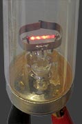
electrodes are used and the current between them is allowed to rise. Shown on the right is a small xenon-filled discharge tube connected across a current-limited high-voltage RF source. As the current is increased, the glow discharge gives way to an arc. Although a still picture cannot show it, the arc also wanders up and down between the electrodes under the influence of convection processes in the gas. |
 Glow |
 Arc |
Structure of the low-pressure gas discharge .
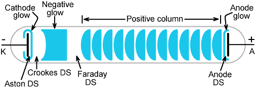
If a gas-discharge tube is connected to a high-voltage DC source, or to an asymmetric (polarised) AC source (such as an induction coil), various structures will be seen in the glowing column depending on the gas pressure, the tube length, and the operating current. Not all of the possible phenomena will necessarily be visible at any one time, but in long tubes there will usually be found a low pressure (ca. 1% of atmospheric pressure or less) at which judicious adjustment of the current will cause the discharge to take on an appearance similar to that depicted below (the glow colour however depends on the type of gas). In some gases also (e.g., neon), the negative glow and the positive column merge and the Faraday dark space is indistinct.

'DS'
is an abbreviation for 'dark space'.
A full explanation of the underlying physics is not appropriate in this brief introductory article; but the structure can be understood on the basis that there is a current of electrons flowing towards the anode, and a current of positive ions migrating towards the cathode. Excitation of gas molecules to energy-states from which they emit light on falling back to the ground-state depends on collisions with ions and electrons; and these charged particles require a period of acceleration in the electric field before they have sufficient energy to cause the required collisional excitation. Also electron production occurs in waves, starting at the cathode as a result of ion bombardment, with subsequent secondary electron production in the gas column (and even at the anode) as a result of collisions. Hence the various light and dark bands.
The phenomena within the tube can be separated into two distinct groups:
Because there are two distinct sets of phenomena visible in the gas discharge; tubes designed for light-emitting purposes are conveniently divided into two types. These are as follows:
In cathode-glow lamps, the positive column glow is usually suppressed by keeping the inter-electrode distance short, and the negative glow can be suppressed by keeping the pressure low to expand the Crookes dark space.
The positive column is made prominent by using a large inter-electrode distance. In positive column lamps, the major dark spaces and any striations can be filled-in by using AC excitation (although judicious choice of pressure, current and frequency is sometimes necessary to make them disappear completely). Also, the efficiency with which electrical energy is converted into light increases with excitation frequency (up to a limit), which is why modern compact fluorescent lamps (CFLs) and neon-sign lamps are operated at several 10s of kHz.
For a given gas, the glow colour obtained in a cathode-glow lamp can be radically different from that obtained in the positive column. This is especially the case when a mixture of gases is used. In cathode-glow lamps, the positive glow is not normally seen, but it can be excited by placing the tube in a strong radio-frequency field. Comparison of the two glows can then reveal the gas mixture. In some nixie tubes for example (see XN12), a mixture of neon and mercury vapour is used. In this case the cathode glow is orange, but the positive glow is blue-green (i.e., cyan). Haze, due to incomplete suppression of the positive glow, can in this case be eliminated by the use of a red filter (the tubes are often dipped in red varnish).
Discharge tube: current vs. voltage characteristic .
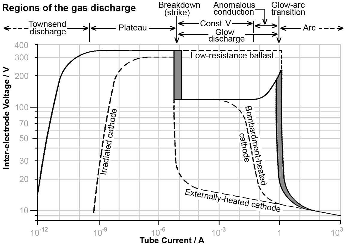
Shown below is a 'typical' current vs. voltage characteristic for a gas discharge tube. The graph is only typical however in the sense that all tubes exhibit the conduction behaviour shown, but the corresponding voltages and currents, and the relative lengths of the various regions, are highly variable. The axes labelled as shown might correspond roughly to the characteristic of a voltage-regulator tube without a priming electrode. The characteristic is obtained by operating the tube from a variable-voltage power supply with a series (ballast) resistance.
Note, incidentally, that the graph is easiest to interpret if it is borne in mind that the voltage is the independent variable, and the current is the measured quantity; i.e., the curve is what happens as we turn the voltage up. Also note that the graph shows transitional events that cannot be reversed by turning the voltage down; i.e.; the curve has hysteresis.

There is some conduction through the tube before it reaches its breakdown or 'strike' point. This is known as the 'Townsend discharge', or 'dark discharge', and is due to ionisation caused by collisions between gas molecules. Increasing the inter-electrode voltage will lead to a point where the current increases dramatically for a very small increase in voltage, and hence a voltage plateau is reached..
Operation in the plateau region is unstable. This is because the electric field is strong-enough to accelerate free electrons to a degree that allows them to ionise gas molecules and liberate more electrons. When the current reaches a critical point, an avalanche effect occurs and the discharge becomes self-sustaining. This is the breakdown point, at which the gas starts to glow, its conductivity suddenly increases, the voltage-drop across the ballast resistance correspondingly increases, and the inter-electrode voltage drops abruptly. The breakdown point is noisy and ill-defined , and so is shown in the graph to be likely to occur over a range of currents. It is also uncertain in time, requiring a random fluctuation to set it off, and so may be delayed for several seconds (or even minutes).
The highest possible plateau voltage prior to striking will not necessarily be reached. If the cathode is illuminated by any ionising EM radiation, or if there are any radioactive events affecting the gas or the cathode, then the tube will strike early. If the tube is kept well away from the breakdown point however, the increase in current due to irradiation is reversible and allows the tube to be used as a radiation detector.
If there is a relatively-high series resistance, the tube will enter the glow discharge region upon striking. If the gas pressure is relatively high, this is characterised by a cathode-glow covering only part of the cathode, and a running voltage that remains nearly constant over a wide range of currents (at least an order-of-magnitude, often more). The glow tends to concentrate at the part of the cathode having the lowest electron-work-function. The rate of electron production is limited however, and so as the current is increased, the glow coverage increases. Often, also, the glow patch is unstable and moves around on the cathode. This is because the gas is not in thermal equilibrium. The hot region around the glow patch reduces the gas density and causes the point of lowest running voltage to move to a new location. Thus the glow tends to flicker, but the phenomenon causes fluctuations only of the order of a few mV in the running voltage, and so does not affect the utility of the tube as a voltage regulator. The flickering effect can be deliberately enhanced however (for novelty flame-effect lamps, etc.) by using special cathode coatings to obtain a uniform work-function.
At the end of the constant voltage (CV) region, comes the point at which the cathode glow coverage is complete. This leads to a region in which further increase in current is accompanied by an increase in running voltage. This, of course, is normal behaviour for ordinary conductors; but gas discharge tubes are regarded as negative-resistance devices, and so this is known as the 'anomalous conduction' or 'abnormal conduction' region. The useful current-range of this region can be increased by keeping the cathode area small and making the gas pressure relatively low (at some cost in terms of light output). Cathode glow lamps that must produce a stable display (such as nixie tubes) are operated in this way. Also, tubes that must quench in response to a reduction in applied voltage (such as glow-switches) are optimised for this region.
At the end of the abnormal conduction region there is another abrupt transition and an arc discharge begins. This is characterised by very high current density and an inter-electrode voltage that falls as the current is increased. The surface electrode temperature is equal to the boiling temperature of the electrode-material or coating, and electrodes must be made of extremely refractory material if they are not to be rapidly consumed. Once again, the current at the onset-point is uncertain.
Note that the existence of a glow-discharge region prior to the onset of arc-conduction is a matter of choice of ballast resistance. If the resistance is low, the tube will pass straight into arc-conduction mode after striking.
A direct transition to an arc-like conduction mode is also obtained in tubes with heated cathodes. The electrical characteristic is that of an arc commencing at an unusually-low current, but whether it should be referred to as an arc is moot. Strictly, an arc is self-sustaining, whereas this type of conduction will change into a glow-discharge if the heater-supply is turned off.
Tubes with thermionic cathodes heated by ion bombardment (fluorescent tubes, etc.) exhibit a variant of arc-like-conduction onset if started without the use of cathode pre-heating. The discharge begins as a glow-discharge, but goes into arc-like conduction mode as soon at the cathode reaches working temperature. For such tubes, there is no anomalous conduction region.
Operating region for various types of discharge tube
| Townsend discharge | Ion (vacuum pressure) gauges Geiger-Müller tubes Gas photocells |
| Constant voltage (CV) glow discharge | Voltage
regulators . Radar T/R switches . Novelty flicker-effect lamps . |
| Anomalous conduction glow discharge | Glow
lamps (indicators and night-lights). Glow switches (fluorescent-lamp starters) Nixie tubes . |
| Arc-like conduction (hot cathode) |
Fluorescent
tubes . Sign tubes . |
| Arc | Flash
tubes and quench tubes . Strobotrons . Spark gaps . HID Lamps . Capillary Spectrum Tubes (referring to the discharge in the capillary) |
Tube oscillations .
Most gas discharge tubes, being negative-resistance devices, tend to oscillate. A simple oscillator can be made, for example, by operating the tube via a ballast resistor and placing a capacitor directly across it. In this case, the ballast resistor charges the capacitor until the strike voltage is reached. Then, assuming that the capacitor has a low internal resistance, the tube goes into arc-conduction mode until the extinction point is reached. The capacitor then recharges and the cycle repeats. This type of circuit is known as a 'relaxation oscillator'.
Relaxation oscillators normaly run at low frequencies, but with some tubes, it is possible to get the circuit to work at several 10s of MHz. The oscillations so produced also tend to have a very large large noise bandwidth, and can be deleterious to radio-signal reception. Hence it is essential that tubes used in radio systems have very low shunt capacitance; this being an important consideration when using nixie tubes in frequency-readout circuits. The basic precaution is to place the ballast resistor directly adjacent to the anode connection, and give this part of the circuit plenty of room on the circuit board.
A more sophisticated negative-resistance oscillator can be made by feeding a DC arc via a choke and placing a series-resonant LC circuit across the tube. If the arc can change its conduction characteristic fast-enough to respond the the resonant oscillation of the LC network, the negative-resistance cancels the losses in the resonator and regenaritive oscillation occurs. This method was used to produce continuous-wave radio signals before the advent of the hard-vacuum triode oscillator (see, for example: 'Alternator Arc and Spark', by Duncan Cadd); although a very fast-quenching arc (hydrogen atmosphere) is required if this is to work at long-wave radio frequencies.
Further information and bibliography:
(3rd edition, 1928, also exists, out of copyright since 2010 but currently not available free).
 The Passage of Electricity
Through Discharge Tubes at Low Pressures.
The Passage of Electricity
Through Discharge Tubes at Low Pressures.R Whiddington.
Science Progress in the 20th Century (1919-1933). Vol 20, No, 80, April 1926, pp 620-636
Available from Jstor.
Interesting discussion of striations (beading) from p633 on.
Historical review of gas discharge tube development. Tubes are clasified into 5 groups: (1) Ionization tubes, (2) Cold-cathode discharge tubes, (3) Hot-cathode arc discharge tubes, (4) Liquid metal arc tubes, and (5) Plasma tubes.
(Thanks to Dr Duncan Cadd (G0UTY) for the donation of this book).
(Review, Oct. 2020, Open Access).
Yu Z Ionikh. https://rdcu.be/cnR5z

|
 Discharge
Tubes Discharge
Tubes |
|

