 |

Discharge-Tube Power Supplies and Ancillary Equipment
| CCFL | Sign Tube | Tesla | Spectrum Tube | Palmer |
Introduction
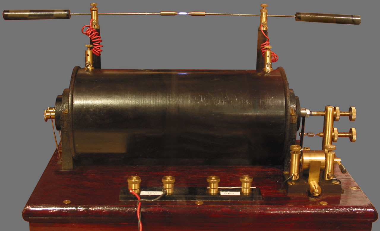 In the days of our long-dead ancestors, discharge tubes
of all types were illuminated by means of a device known as a
Ruhmkorff coil.
This is a large-ratio step-up transformer, driven by a low voltage DC supply
(Leclanché or Pb:H2SO4
cells) with a magnetic interrupter (i.e., a
buzzer). Much good science was done in this way, and the old-fashioned
spark-generator still has a lot to recommend it; but
technology has, for worse or worse-still, moved on. The modern
inverter PSU is still a step-up transformer, but based on a ferrite core and
operated at 10s of kHz, and the interrupter is an electronic circuit involving
one or more switching transistors. The results should be unequivocally
better than those of 100 or more years ago; but such is not
always the case, and an understanding of relevant issues is strongly
advised.
In the days of our long-dead ancestors, discharge tubes
of all types were illuminated by means of a device known as a
Ruhmkorff coil.
This is a large-ratio step-up transformer, driven by a low voltage DC supply
(Leclanché or Pb:H2SO4
cells) with a magnetic interrupter (i.e., a
buzzer). Much good science was done in this way, and the old-fashioned
spark-generator still has a lot to recommend it; but
technology has, for worse or worse-still, moved on. The modern
inverter PSU is still a step-up transformer, but based on a ferrite core and
operated at 10s of kHz, and the interrupter is an electronic circuit involving
one or more switching transistors. The results should be unequivocally
better than those of 100 or more years ago; but such is not
always the case, and an understanding of relevant issues is strongly
advised.The Ruhmkorff coil can be categorised as a type of 'leakage transformer'. The primary and secondary coils are concentric solenoids, with the inner of the smaller (primary) coil packed with lengths of varnished iron wire (the insulation prevents eddy currents). The wires do not protrude beyond the ends of the solenoid, and so the magnetic circuit is completed over a large distance in the surrounding air. Hence the output has an approximate constant-current characteristic, as required by discharge tubes, and can be shorted-out with impunity.
Many years ago, before switched-mode PSUs, there were neon signs everywhere in high streets and shopping centres. These tubes were run in constant-current mode at mains frequency using HV transformers designed to have very high leakage inductance (shunt transformers). The term 'leakage transformer' was coined in this context. Every shop had to have a big red Fire Switch by the entrance, so that the Fire Brigade could switch off the nasty HV source before going-in. In many instances, the nasty HV source was also the cause of the fire. Those were the days!
CCFL Inverters
The term 'CCFL' (cold-cathode fluorescent lamp) is something of a misnomer, because Mercury vapour fluorescent tubes generally have oxide-coated cathodes that can be pre-heated to get the tube to start at low (i.e., mains) voltage. The cathodes will then continue to glow when operated with adequate current. Of course, the household mains supply has insufficient leakage reactance to make it behave as a quasi constant-current source, but it can be given the equivalent of leakage inductance by placing a choke in series with the lamp.
The CCFL power-supply of interest when experimenting with discharge tubes however is not the series choke, but the high-frequency inverter; as used to run emergency lights during power failure, and as used to run fluorescent tubes from vehicle batteries. These devices do not use the cathode pre-heat method to start the tube, but instead rely on high off-load output voltage, and leakage reactance to limit the current once the tube starts conducting. The use of a shunt transformer is feasible in this context; and gapped-core transformers are also used. A simple and cheap alternative however is to place one or more high-voltage capacitors in series with the tube. The ability to select different capacitors allows several tube sizes to be accommodated.
Since CCFL inverters have characteristics very similar to those of sign tube and spectrum tube PSUs, they can be used to run a variety of tubes. They can also frequently be obtained for no money as a result of building upgrades.
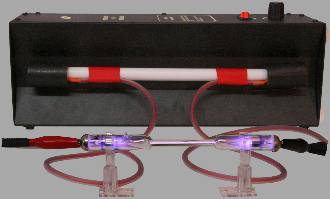
Shown below is an old S484/40 emergency exit-light inverter, one of several given to the author some years ago. The panel with the information sticker is a lid that covers the electronics.
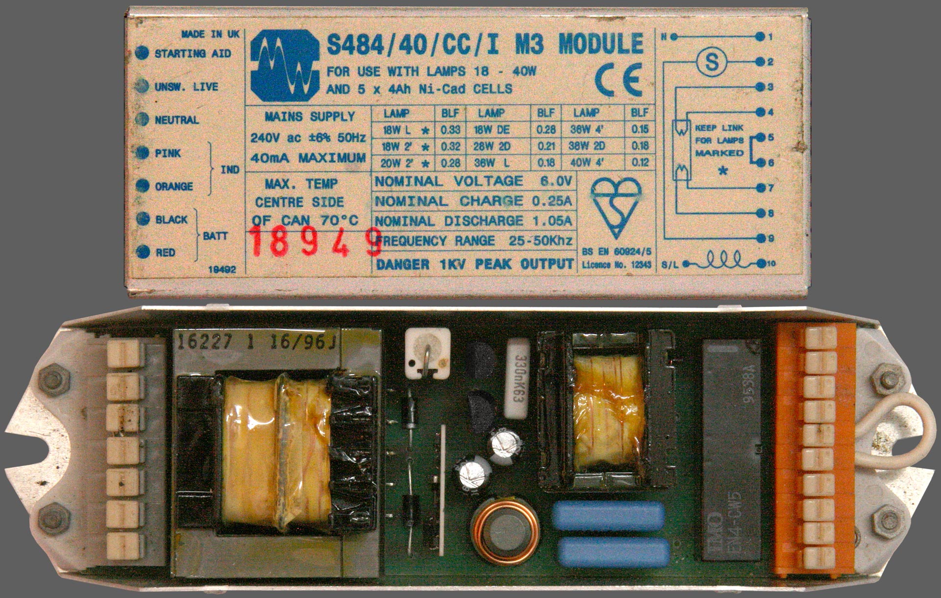
This module is designed to detect power failure and switch a fluorescent tube over to an inverter powered by 5 Ni:Cd cells (6V nom.). It can run FL tubes up to 4' (1.22m) in length, with ratings of 18 to 40W depending on selection by means of a link wire. The transformer on the left, along with 2 diodes and a power resistor, is the battery charger. The black rectangulare component on the right is the change-over relay. The inverter lies between those sections. It uses 2 × BCU83 transistors to drive an un-gapped ferrite transformer, with the oscillator on a surface-mount module. Running frequency is between 25 and 50 kHz. The ferrite choke is for radio interference suppression. The two blue capacitors are both 1nF, rated 1250 Vac at 400 Hz. They provide the tube ballast and are wired in series. The link allows one of the capacitors to be shorted-out. The off-load output voltage of 1kV allows the inverter to start fairly long Hg:Ar sign tubes, and the on-load output is sufficient to run them at full brightness.
The S484 is a straightforward and robust inverter but, from an experimenter's perspective, it comes with a lot of extraneous junk and can be made more versatile. The circuit board below has therefore been stripped of everything except the inverter, with the ballast arrangement selectable by choice of output connection. Moving one of the wires between terminals allows the use of 0, 1 or 2 capacitors in series (∞, 1nF or 500pF). Linking across 2 terminals also allows the capacitors to be used in parallel (2nF). Connection with no ballast allows a variable capacitor to be used, although it needs to be fully insulated and capable of withstanding > 1kV ac.
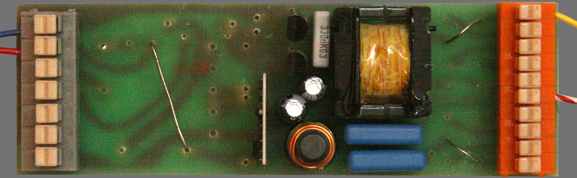
Operating the inverter is a simple matter of using a lab PSU to apply a maximum of 6V DC to the input. Additional versatility also comes from the fact that the input voltage can be used to vary the pre-ballast HV output. The saturation voltage of the BCU83 transistor is about 0.5V, so the output is given to a fair approximation by:
Vout = Vmax (Vin - 0.5) / (6 - 0.5)
i.e.,
Vout = Vmax (Vin - 0.5) / (5.5)
Vmax is about 1kV peak (at the recommended maximum of 6V DC in)
The stripped-down inverter shown was used in some of the author's initial experiments with sign tubes. Those experiments are described in detail on the sign tubes page. It proved perfectly capable of running a 0.64m Hg-Ar sign tube, and it was able to run a 0.64m pure neon tube by the addition of an external priming electrode. The special arrangement required for starting a long neon tube does however reflect the fact that this inverter cannot start tubes that require a high initial voltage, and it cannot run tubes that have an operating voltage >1kV peak ac. In the event that running is possible, but starting is problematic, there are various work-arounds. One of the simplest solutions is to bring the tube close to a miniature Tesla coil until it strikes, then move it away or turn the Tesla coil off. It is important however not to let a powerful Tesla coil spark onto the wall of the tube, since that can cause leaks.
>>>> more planned
-- pictures of tubes being operated via a 1000 pF variable capacitor ballast.
-- other small inverters
Mini Tesla Coil
-- Picture and circuit diagram
-- electrodeless tubes
-- starting a tube that won't strike on an FL inverter
 There is such a thing as an HF vacuum leak detector, which is a hand
held Tela coil producing several 10s of kV. The saying in the research
labs and industry is that these devices are "good for leaks", in the
sense that, if you don't have any leaks, letting one spark onto your
glasswork will give you some. Leak detectors and other Tela coils must
only be allowed to spark onto glass in places where leaks are already
known to exist. The spark trail will then give the exact
location.
There is such a thing as an HF vacuum leak detector, which is a hand
held Tela coil producing several 10s of kV. The saying in the research
labs and industry is that these devices are "good for leaks", in the
sense that, if you don't have any leaks, letting one spark onto your
glasswork will give you some. Leak detectors and other Tela coils must
only be allowed to spark onto glass in places where leaks are already
known to exist. The spark trail will then give the exact
location.Peter Jameson adds: When signmakers need to bring a phosphor-coated tube up to atmosperic pressure gently (in order not to blow-off the coating), an option is to pierce one of the electrode shells with an HF leak detector. After that, the tube will come slowly up to atmospheric pressure. The electrodes can then be cut-off and replaced, giving the tube a new lease of life.
Sign Tube Power Supplies
XingXing ENT-103A
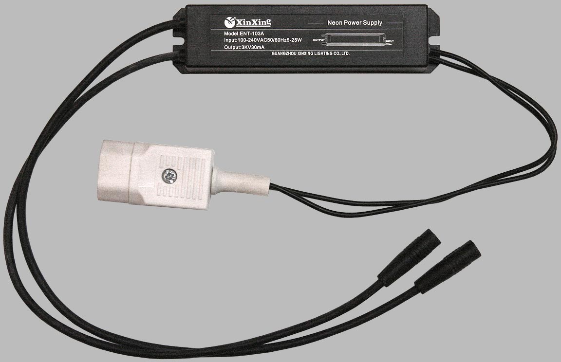
This power supply is available under various brand names, but the details are in the spec.. It runs from a household AC supply of between 100 and 240V AC and, bearing in mind that positive-column light sources have an approximately constant-current characteristic, it can produce up to 3kV for starting, and a running current of 30mA. It can therefore run a series-string of sign tubes of a couple of metres length; but it also doesn't care about short circuits and so can run low voltage lamps for testing purposes. (
Do not
use a sign tube PSU to run Sodium lamps, they
suffer permanent cathode damage if the current is too low). The
stated power output of 25W implies a maximum operating voltage
of about 830V at full current, so Hg-Ar tubes are to be preferred over
Neon in long
strings. The ENT-103A is potted in resin and therefore reasonably damp
proof. There is, of course, a danger of electric shock - especially if
it is operated open circuit. The IEC male input connector and 4mm free
sockets are not supplied as standard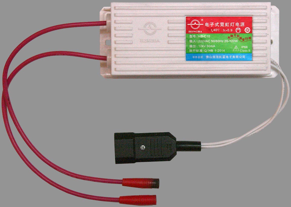
This is a high-output PSU, producing up to 10kV for starting, and a maximum of 120W at 30mA. This implies that it can operate strings of sign tubes requiring a running voltage of 4kV, which means that it is better suited to the higher voltage requirements of Neon.
Note the burn mark on the end of one of the 4mm sockets (the other has one as well but it is turned away from the camera). This is what happens if the PSU is absent-mindedly plugged-in without a load.
Since this PSU can produce more than 6kV, users should be aware of the risk of X-ray exposure.
Hongba HB-C05TE-DM (Dimmable).
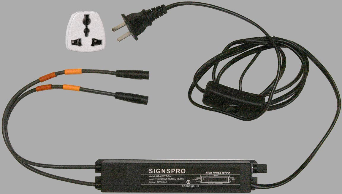
The unit shown is branded Signspro, but the HB prefix indicates that it was made by Hongba. This is probably one of the most useful commercial discharge-tube PSUs ever made because it has a control enabling the running current to be adjusted between about 3 and 30 mA. This means that it can be used both to run sign-tubes and spectrum-tubes; and spectrum tubes that would sputter and die in short-order on a conventional tube-holder PSU can be run for moderately-long periods without damage. The author once accidentally left an Iodine spectrum tube running on the minimum setting for ca. 90 mins, and it was completely unharmed.
The PSU produces 5kV for starting, and has a maximum output of 30W. It can therfore run strings of tubes requiring up to 1kV. Mains input is 100 - 240Vac, 50 or 60 Hz, and the in-line switch and plug are provided. For the UK, a flat-pin adapter (e.g., as shown) is required.
To obtain this item, search "HB-C05TE-DM" on AliExpress. The required color is "with dimmer".
-- spectrum tubes running on the HB-CO5TE-DM
26cm Spectrum Tube Power Supplies and Accessories
Tube Holder PSU
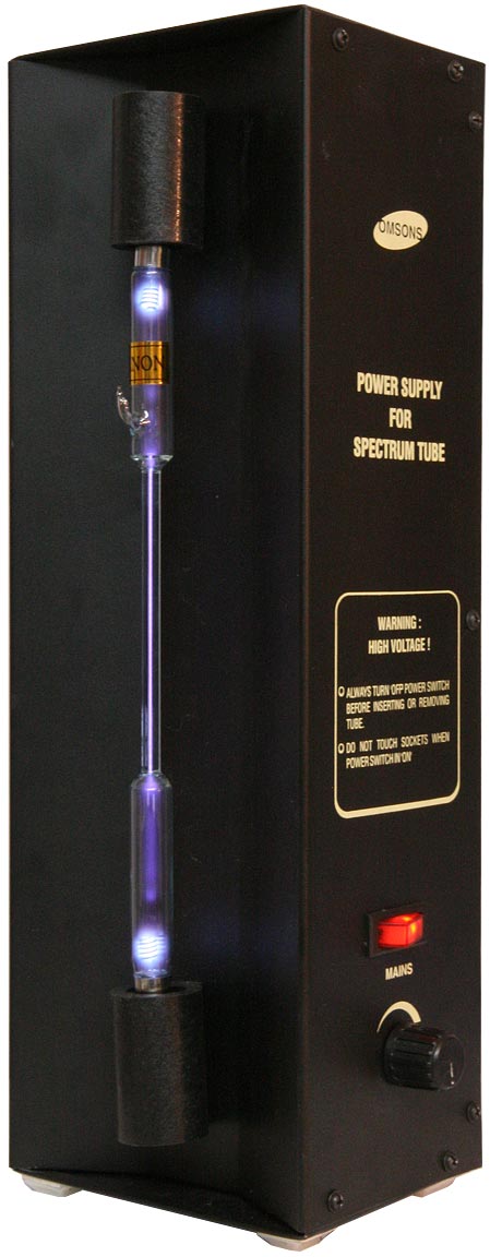
Shown on the right is a
spectrum-tube PSU of Indian origin,
decorated with the brand logo 'Omsons'. This has a built-in holder for
26cm 'standard' tubes, and there is no way of connecting to the output
other than via the tube holder. Vast numbers of very similar-looking power
supplies have been sold to Schools and Educational Establishments, and
yet this particular device deserves an award for being one of the most
ill-concieved pieces of lab equipment ever to have been released on to
the market. If you are thinking of buying one of these, go
and lie down in a darkened room until the feeling goes away.The PSU has a knob on the side, allegedly allowing the life of the tube to be increased by reducung its brightness. This facility however simply does not work. Apart from the occasional sweet spot, anything other than the full brightness setting results in flickering, highly intermittent, operation. Full brightness however over-runs the tube, making it extremely hot and beginning the irreversible electrode-sputtering process in just a few seconds.
On dismantling the PSU to see what was inside it, the mystery of its awfulness was revealed. It consists of a neon-sign PSU operated via a tungsten-lamp triac dimmer circuit. As anyone who has ever tried to operate a CFL or LED lamp from a dimmer-switch will know, placing two switch-mode circuits in tandem results in beat effects, which give rise to strobing and flickering when the duty-cycle is reduced. A neon PSU on full however, passes about 30mA through the tube, causing a spectrum tube to dissippate something in the region of 30W.
I had the misfortune to buy the Omsons PSU from a seller on ebay calling itself 'Scientific Store'. The purchase also included 10 spectrum tubes; but when I received them there were only 5 different types: two each of He, N2, H2, Ar and Hg, and one of the Hg tubes had a cracked sealing stem. The supplier had also messed-up the Customs paperwork, and I was charged an additional 30% on top of the purchase price. I naturally complained that the order had not been properly fulfilled, and was told that more types of spectrum tube would be sent forthwith, this time with correct paperwork. Nothing happened of course. For a while also, I still entertaied the ludicrous fantasy that the PSU was under warranty, and so did not open it to find out why it harmed tubes and did not work properly. Some months after my complaint, I discovered that the seller was no longer registered on ebay.
It is, of course, not necessarily the case that all tube-holder PSUs are of bad design. The problem of finding-out whether they are or not prior to purchase does however seem insurmountable. Given that there are alternative ways to power spectrum tubes (particularly the Hongba HB-C05TE-DM), an instruction to the effect that tubes should not be operated for longer than 30 sec is a strong counter-indication.
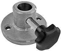
Tube power supply break-out adapter
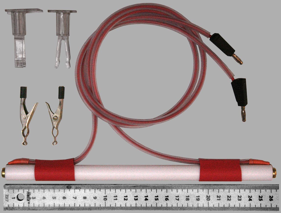
Not all tubes will fit into a 26cm tube-holder PSU, and so for items capable of withstanding the output, it is useful to have a means of connecting to them. The adapter shown above is a 256mm long, 15mm diam. PTFE rod, with the ends drilled and tapped M6. Plain brass dome-head screws with solder tags have then been added and leads attached. The wires are fine strand (ultra flex) test-lead cable, with an outer sleeve of 3mm ID silicone tubing for added insulation. Heat-shrink tubing holds the leads onto the rod to prevent stress on the soldered joints.
Also shown are transparent tube supports, capable of holding diameters from 6 to 20mm; and some test-lead clips (4mm socket) that came with a Russian multimeter bought by the author in the 1970s. The test clips are ideally shaped for connecting to the end caps of a wide variety of tubes, but unfortunately there seems to be nothing similar currently available. Car-battery-charger clips can achieve the required opening, but most are too brutal for the task.
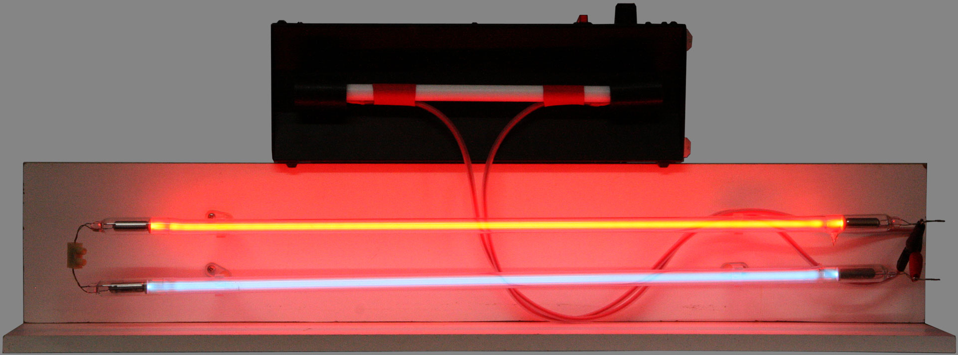
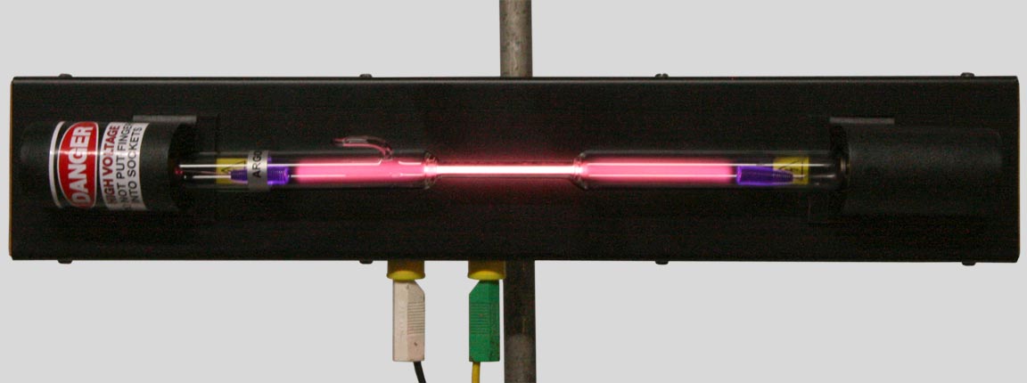
Shown below is the break-out adapter running a Russian 19cm Kr spectrum tube from the Omsons PSU. Unfortunately, some sputtering has occured in the few seconds it took to set the camera exposure and take the photograph.
Spectrum tubes with coiled Ni wire electrodes can withstand the output of the PSU for short periods without noticeable damage, but other metals do not fare so well. Note that sputtering also getters the tube, reducing the internal pressure and changing the characteristics. The Omsons PSU will however run sign tubes, and tubes with rare-earth oxide-coated electrodes (such as Peter Jameson's), and it can be used to power Hg-vapour street-lamp tubes at very low brightness. A Siemens Sieray lamp, for example, is a good source for the Hg calibration lines at 436 and 546nm.
The picture below shows the Omsons PSU running 1.3m of sign tubes at full brightness (42 kHz). Somehow, it comes to mind that this power supply should not be allowed anywhere near to a precious collection of spectrum tubes.
Eisco PH1197B 26cm tube holder
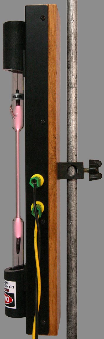 Shown above and right is the Eisco PH1197B holder
for standard 26cm spectrum tubes. This can be connected to any power
supply (even ones that do not destroy tubes) via two high-voltage 4mm
sockets, and the unit is designed to be mounted
on a laboratory retort stand of ≤13mm bar diameter.
Shown above and right is the Eisco PH1197B holder
for standard 26cm spectrum tubes. This can be connected to any power
supply (even ones that do not destroy tubes) via two high-voltage 4mm
sockets, and the unit is designed to be mounted
on a laboratory retort stand of ≤13mm bar diameter.
One
limitation on receiving the holder is that the rear clamping boss is
only drilled for vertical mounting. A few minutes spent drilling an
extra 13mm hole across the boss however gives the ability to mount the
unit either vertically or horizontally. More versatile still would have
been to have a short ½" rod protruding at the back,
allowing the
holder to be fixed to the lab-stand at any angle by means of a standard
boss. One way to achieve that would be to remove the original fitting
and screw a laboratory-frame rod-foot in its place. A short stub of
12.7 mm Ø rod could then be inserted into the foot.
Note that the ability to mount the tube horizontally is important when there is an internal reservoir of solid or liquid material. Horizontal mounting prevents the condensed element or compound from migrating into the capillary. Solid obstructions that have occurred as a result of vertical running can also be cleared by a session of horizontal operation.
Palmer Mutual Inductance Apparatus
The Palmer Induction Coil is essentially a Ruhmkorff Coil, but with a dovetail slider allowing the secondary coil to be moved away from the primary. This allows it to be used to demonstrate the inverse-square law of magnetic induction. The step-up ratio is also much less than that of a typical Ruhmkorff coil, but it can still generate sufficient output voltage to operate a variety of discharge tubes.
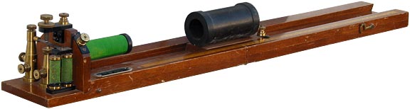
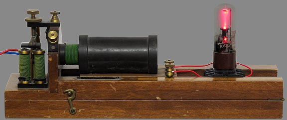
The Palmer Induction coil
is shown on the right producing a positive-column discharge in a Ferranti
NSP2
Neon Strobotron. In this case, the magnetic interrupter
(buzzer)
was used, with a power-supply of 1.5 V DC.
-- Demo using a 3W output audio osc at 8kHz to light a spectrum tube
 X-ray warning:
Most discharge tubes run at relatively low voltage (< 1kV) and are only dangerous in respect of electric shock and possuble UV-C emissions from silica-walled tubes. When experimenting with high degrees of evacuation however, such as can be attained using a Pohl tube and a good vacuum pump, it is possible to create situations in which the tube will run at ≥ 5kV. Under such circumstances, tubes produce X-rays, and can become particularly hazardous at > 6kV.
Note that TV Cathode-Ray Tubes (12 - 24 kV anode potential) and any associated thermionic rectifiers (such as the old-fashioned EY51 - see links below) can also produce X-rays when operated without shielding. This is worth remembering when experimenting with LOPTs and Tesla coils.
Vacuum capacitors with voltage ratings in excess of 5 kV are also a possible hazard when operated close to the breakdown point.
X-rays are ionising (short wavelength) electromagnetic radiation, which can be detected by an end-window-tube Geiger-Müller counter.
External Links:
 Evertron
Sign-Tube PSU Schematic. Product
Manual (X-ray warning).
Evertron
Sign-Tube PSU Schematic. Product
Manual (X-ray warning).EY51 rectifier
| |
